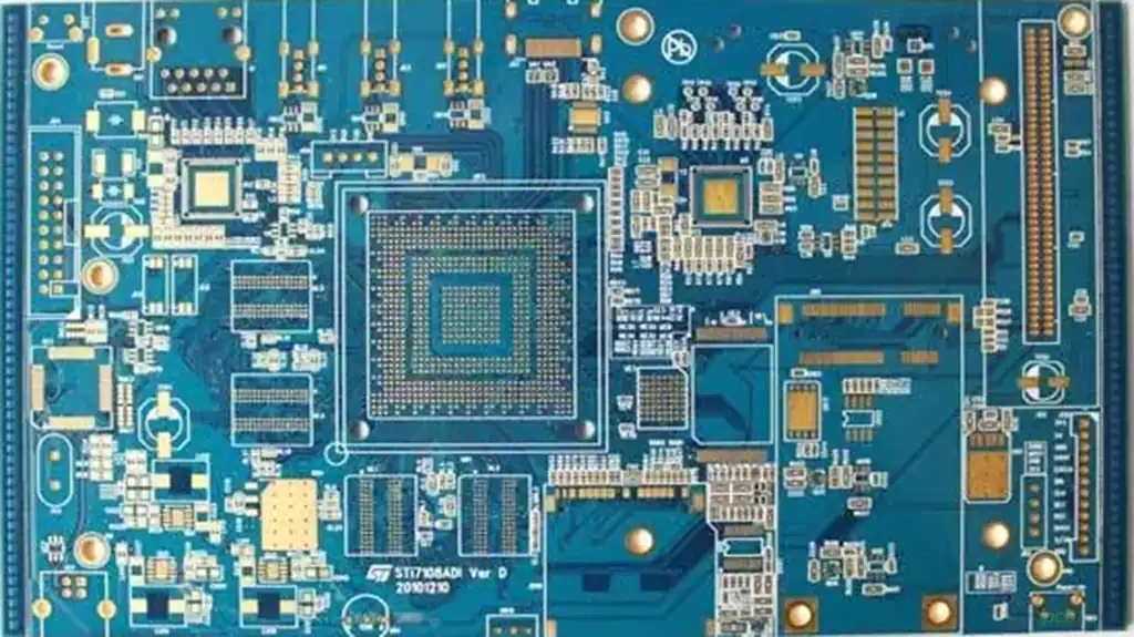
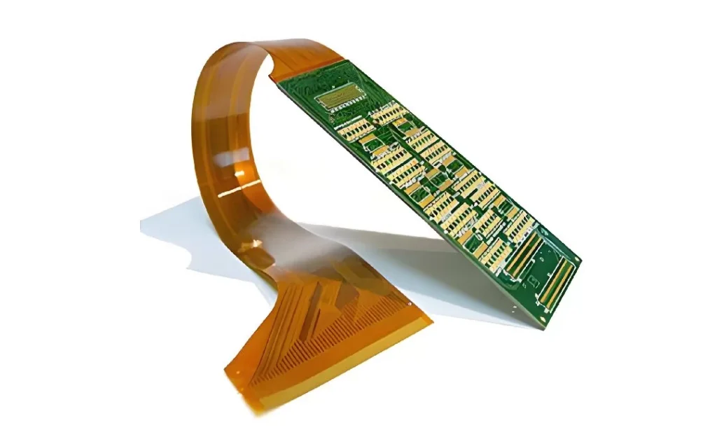
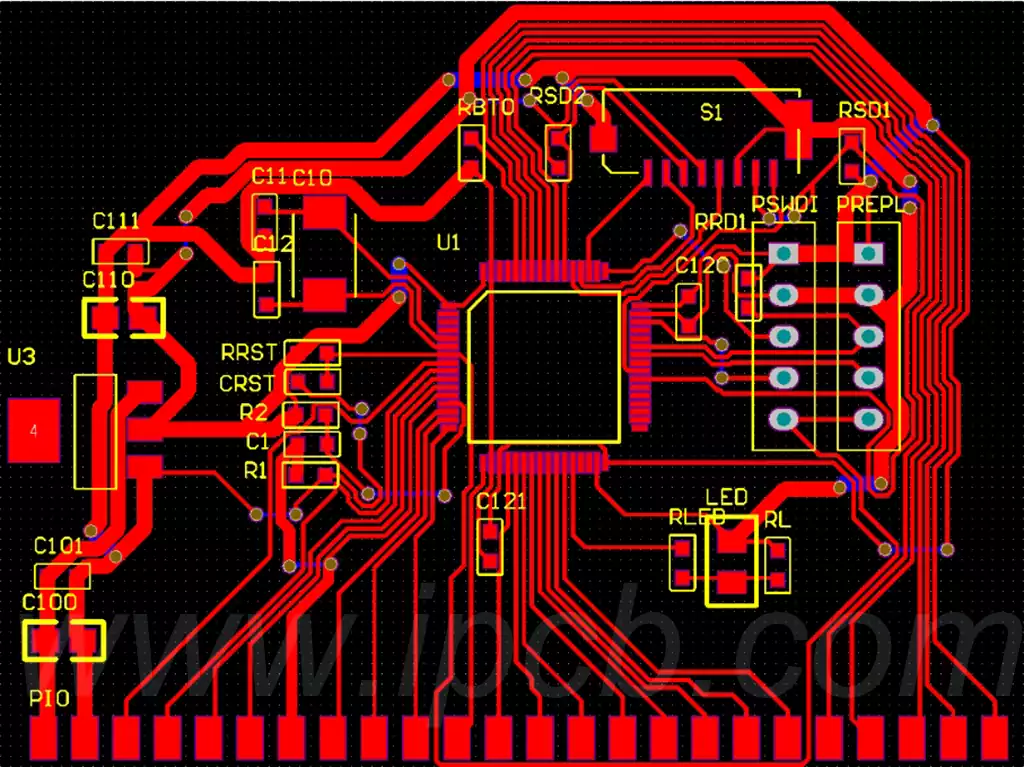
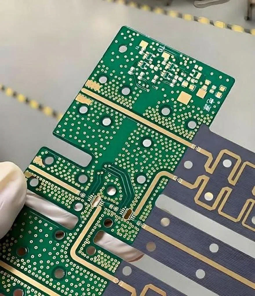
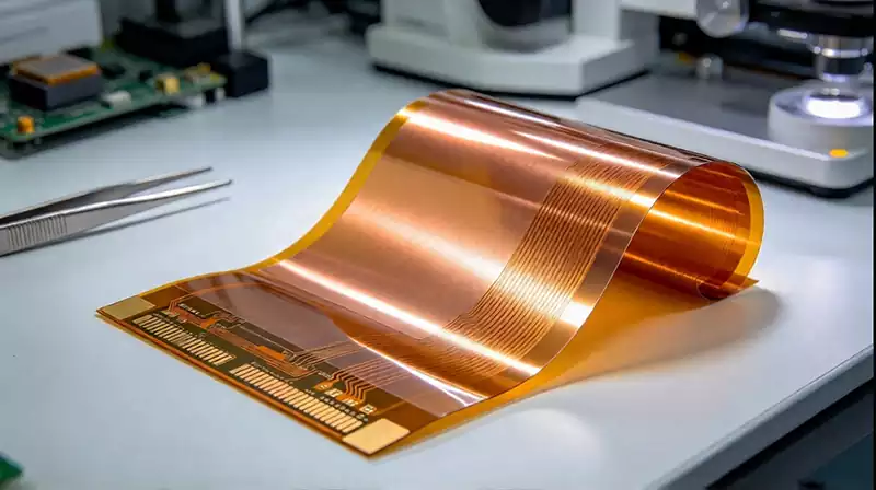
What is an FPC Board? FPC stands for Flexible Printed Circuit. The terms FPC board, flexible PCB, flexible circuit board, and flex circuit are commonly used to describe this type of circuit. Its basic purpose is the same as that of a rigid PCB: it provides conductive paths between electronic components and electrical interfaces. The main difference is that the circuit is constructed on a flexible substrate rather than a rigid board material.
A typical FPC board structure consists of a flexible dielectric substrate, copper conductors, and a protective coverlay or cover layer. Depending on the design, additional layers may be added to create a double-sided or multilayer structure. Connector fingers and other exposed areas can receive suitable surface finishes, while stiffeners may be added where additional mechanical support is required.
Polyimide is widely used as a flexible dielectric material because it can provide the thermal and mechanical properties needed for flexible circuit applications. The choice of material, copper construction, adhesive system, and coverlay depends on the electrical performance, bending requirements, operating environment, and manufacturing process.
The flexible structure changes how the circuit behaves mechanically. A trace that is acceptable on a rigid PCB may experience repeated mechanical stress when placed in a bending region of an FPC. For that reason, the electrical layout and mechanical design need to be considered together from the beginning of the project.
FPC Board Structure and Materials
The construction of an FPC board depends on how the finished circuit will be used. Single-sided FPCs have conductive material on one side of the flexible dielectric, while double-sided versions provide conductive layers on both sides with interconnections between them. Multilayer flexible circuits use additional conductive and dielectric layers when the design requires greater routing density or more complex electrical connections. IPC-2223 identifies several flexible and rigid-flex construction types, including single-sided, double-sided, multilayer, and rigid-flex structures.
Copper is normally used for the conductive layer, but its thickness and construction can vary according to current capacity, flexibility, impedance requirements, and manufacturing constraints. The dielectric thickness also affects the overall flexibility of the circuit. A thinner construction may provide greater flexibility, while a thicker structure can provide additional mechanical strength. The correct balance depends on the intended application.
Coverlay is another important part of many FPC constructions. It protects the circuit traces and provides insulation while leaving selected areas exposed for soldering or electrical connection. Stiffeners can also be added to connector regions or component areas where the flexible material needs additional support.
Material selection becomes particularly important when an FPC must operate in a demanding environment. Temperature, repeated bending, chemical exposure, electrical requirements, and assembly conditions can all influence the appropriate construction. IPC’s flexible PCB design training also identifies material selection, construction type, mechanical retention, signal integrity, and conductor stress as key areas in FPC design.
FPC Board Design Considerations
The mechanical behavior of an FPC board should be considered while routing the circuit. The bend area is not simply another section of the PCB layout because repeated bending can place mechanical stress on copper conductors, pads, vias, and component connections. The design therefore needs to define where the circuit can bend and how the conductors will pass through that region.
Trace routing is especially important in dynamic or repeated-flex applications. Sudden changes in conductor geometry can create areas of concentrated mechanical stress. Designers should also consider conductor spacing, layer transitions, vias, and the relationship between the copper pattern and the bending direction. IPC-2223 includes guidance on conductor routing, conductor edge spacing, differential pair geometry, bend ratio, and flexible-section construction.
Components and rigid features should be kept away from areas that are intended to flex unless the design specifically accounts for the resulting mechanical stress. Connector areas often use stiffeners because the circuit must remain stable when inserted, removed, or held by a mating connector. The transition between rigid and flexible regions also needs to be designed so that mechanical loads are not concentrated at a single point.
Electrical performance can introduce additional requirements. High-speed or controlled-impedance FPCs require appropriate control of dielectric thickness, conductor geometry, reference structures, and routing. Flexible circuits can therefore require both mechanical and signal-integrity analysis, particularly when they are used for high-speed digital or RF signals. IPC identifies signal integrity and the effects of bending stresses on conductive patterns as important aspects of flexible circuit design.
FPC Board Manufacturing Process
FPC manufacturing uses many of the same basic concepts found in conventional PCB fabrication, but the flexible materials require processes and handling methods suited to thin and bendable structures. A typical process can include material preparation, drilling or laser processing, copper pattern formation, plating, etching, coverlay application, surface finishing, profiling, inspection, and electrical testing. The exact sequence varies with the FPC construction.
For example, a double-sided flexible circuit can use a flexible copper-clad material as its starting structure. Through-holes can be formed and plated to connect the conductive layers, followed by circuit imaging and etching. Flexible areas can then be protected with a cover layer. IPC technical documentation describes flexible circuit fabrication using polyimide-based copper-clad materials, drilling, electroplating, circuit formation, and heat-pressed cover layers.
Manufacturing inspection needs to cover both electrical and mechanical requirements. Electrical testing can verify continuity and isolation, while dimensional inspection checks the circuit outline, holes, pads, connector features, and other critical geometry. For applications involving repeated flexing, the mechanical construction and bend regions also require careful review.
The manufacturing files need to communicate the flexible regions and construction clearly. Layer definitions, board outline, bend areas, coverlay openings, stiffeners, surface finishes, and other special requirements should be documented consistently. A well-defined design makes it easier to review manufacturability before production and reduces the risk of differences between the intended design and the manufactured FPC board.
An FPC board is therefore more than a rigid PCB made from a thinner material. Its flexible construction changes the relationship between electrical layout, material selection, mechanical movement, assembly, and manufacturing. When these factors are considered together, a flexible circuit can provide reliable electrical connections while fitting into products that require compact, lightweight, or three-dimensional electronic assemblies.