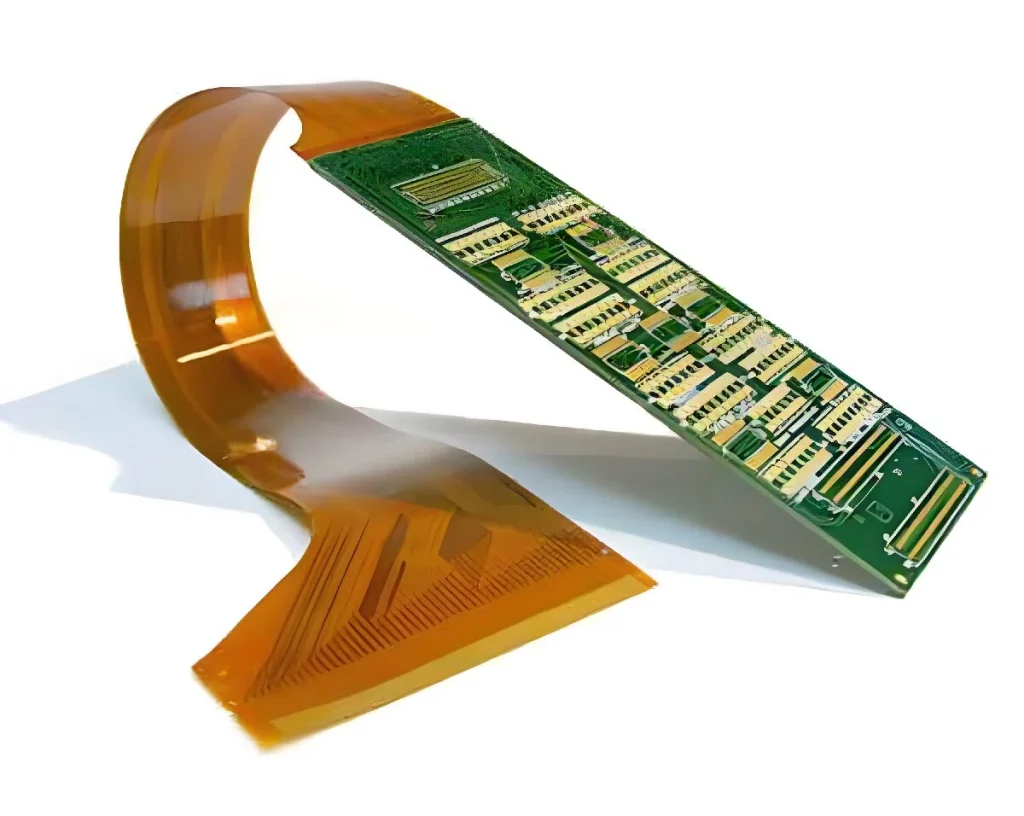
There is a significant difference between FPC PCB assembly and the assembly of rigid circuit boards, the main reason is that flex board is softer and less hard, if you do not use a special carrier board, it is difficult to achieve effective fixation and handling, so as to be unable to complete the printing, mounting and reflow soldering and other key SMT process steps.
Pre-treatment of flex board
Since flex board is relatively soft and usually non-vacuum packaged, they are prone to moisture absorption during transport and storage, so they must be pre-baked before they are put on line in SMT to slowly expel the absorbed moisture. Without this treatment, moisture evaporates into vapour during high-temperature reflow soldering, which can lead to delamination, bubbles and other defects in the FPC.
Fabrication of Specialised Carrier Boards
Based on the circuit board CAD file, a high-precision positioning template and a special carrier board are fabricated using the aperture data of the flex board. The diameter of the positioning pins on the template should match the positioning apertures of the carrier board and FPC. Considering the uneven thickness of different areas of the FPC and the possibility of adding metal reinforcement plates, the bonding area between the carrier plate and the FPC needs customised processing, such as sanding or grooving, to ensure that the flex board is flat during printing and mounting. The carrier plate material should be lightweight, high strength, low heat absorption and fast heat dissipation, and not easy to be deformed after many thermal cycles, commonly used materials are synthetic stone, aluminium plate, silicone plate and high temperature magnetized steel plate.
Production Process
Introducing flex board SMT key points with a common carrier board as an example. When using silicone board or magnetic fixture, FPC fixation is more convenient and no tape is needed, but the process requirements for printing, mounting and welding are the same.
1.FPC fixing
Before SMT, the flex board must be accurately fixed on the carrier board, and the time from fixing to printing mounting and soldering should be as short as possible. Carrier plate is divided into two kinds of positioning pins and without positioning pins: carrier plate without positioning pins need to be used with a template with positioning pins, the carrier plate on the template pins, through the holes in the carrier plate will be exposed to the positioning pins, and then FPC covered in the positioning pins and fixed with tape, and then remove the positioning templates for subsequent processes; with positioning pins on the carrier plate with a spring-loaded pin of about 1.5mm in length, you can directly set the FPC in the pin and fixed with tape. The spring loaded pin does not affect the printed stencil. The spring-loaded positioning pin does not affect the printing stencil pressing effect.
Single-sided tape fixing: Use high-temperature-resistant thin single-sided tape to fix the four sides of the flex board to prevent shifting and warping, and the viscosity of the tape should be moderate, so that it can be easily peeled off without residual adhesive after reflow soldering. Automatic tape machine can cut the tape quickly to improve efficiency and save money.
Double-sided adhesive tape fixing: Firstly, stick the high temperature resistant double-sided adhesive tape on the carrier board, and then stick the flex board therein. The viscosity of the tape should not be too high, otherwise it is easy to tear FPC when it is peeled off after reflow soldering. the viscosity of the tape decreases after repeated ovens, and it must be replaced in time when it fails to meet the fixing requirements. The workstation to prevent FPC contamination is the key, the operation needs to wear finger cots, repeated use of the carrier board before cleaning and dust removal, and pick and place the FPC movements need to be gentle, to avoid creases and breakage.
2.FPC solder paste printing
FPC on the composition of the solder paste is not particularly stringent requirements, the size of its tin ball and metal content according to the FPC components on the fine degree of determination. Solder paste needs to have excellent thixotropy, to ensure good print release performance and good adhesion, does not block the screen or printing after the collapse and other defects.
Printing due to the FPC fixed caused by the carrier board surface is not flat, can not be as flat and consistent as the PCB, so it is not suitable for metal squeegee, but the hardness of 80-90 degrees of polyurethane squeegee. It is recommended to use the printing machine with optical positioning system to ensure the printing quality, and need to accurately adjust the parameters of the equipment to adapt to the FPC and the carrier board between the existence of small gaps. The printing area should be cleaned and prevented from contamination.
3.FPC placement
According to the product demand and the number of components, can use medium and high speed placement machine placement. Flex board is equipped with optical positioning MARK mark, placement process is similar to the hard board. However, due to the FPC surface is not flat and there is a gap between the carrier board, you need to accurately adjust the height of the suction nozzle drop, blowing pressure and moving speed.
4.FPC reflow soldering
uses forced hot air convection infrared reflow oven to ensure uniform flex board temperature and reduce soldering defects. If one-sided tape is used to fix only the four sides of the FPC, the middle part will be deformed by heat, resulting in tilted pads and abnormal flow of tin, causing empty soldering, continuous soldering and beads, increasing the defective rate.
Temperature profile test: Because the carrier board and component heat absorption differences, need to accurately set the reflow temperature profile. Usually used in the production line before and after the test board placed in a number of FPC carrier board, next to the component welding high temperature temperature probe to collect data, pay attention to the temperature near the edge of the carrier board and the important soldering point, to ensure that the data reflect the real soldering conditions.
Temperature profile setting: In order to control the thermal shock, it is recommended to use the heating, holding, reflux segmentation curve. Set the temperature more adjusted to the lower limit of the technical specifications of the solder paste, reflow furnace wind speed to the lowest, while ensuring that the furnace chain chain is stable, no obvious jitter.
5.FPC inspection, testing and distribution of boards
Due to the heat absorption of the carrier plate, especially the higher temperature of the aluminium carrier plate, it is recommended that the furnace mouth to increase the mandatory cooling fan, the operator needs to bring heat-insulating gloves in order to prevent burns. When removing the board should be even strength, avoid using brute force to prevent FPC tearing or creasing.
After welding flex board should be at least 5 times under the magnifying glass carefully visual inspection, focusing on checking the residual glue, colour change, gold finger tin stagnation, tin beads and solder joints, such as empty welding, continuous welding. Because the surface is not flat enough, AOI misjudgment rate is high, so usually do not use AOI inspection, but with the help of special test fixtures for ICT and FCT test.
FPC PCB Assembly Process is mostly in the form of joint boards, which need to be divided into boards before testing. Although it can be done manually with blades or scissors, the efficiency and quality are limited. Shaped FPC mass production, we recommend the use of special stamping board moulds to improve efficiency and cutting edges neatly, reduce stress in the solder joints to avoid tin cracks.
FPC PCB assembly soldering process, the key to accurate positioning and effective fixation, relying on the appropriate special carrier board design. Pre-baking treatment, solder paste printing, placement and reflow soldering and other aspects of the process is complex, the difficulty is much higher than the hard PCB, so the setting of accurate process parameters and strict implementation of SOPs, while strengthening the production process monitoring and inspection, is to reduce the defective rate to ensure product quality necessary measures, ideally, can be controlled in the defective rate of dozens of PPM or less.