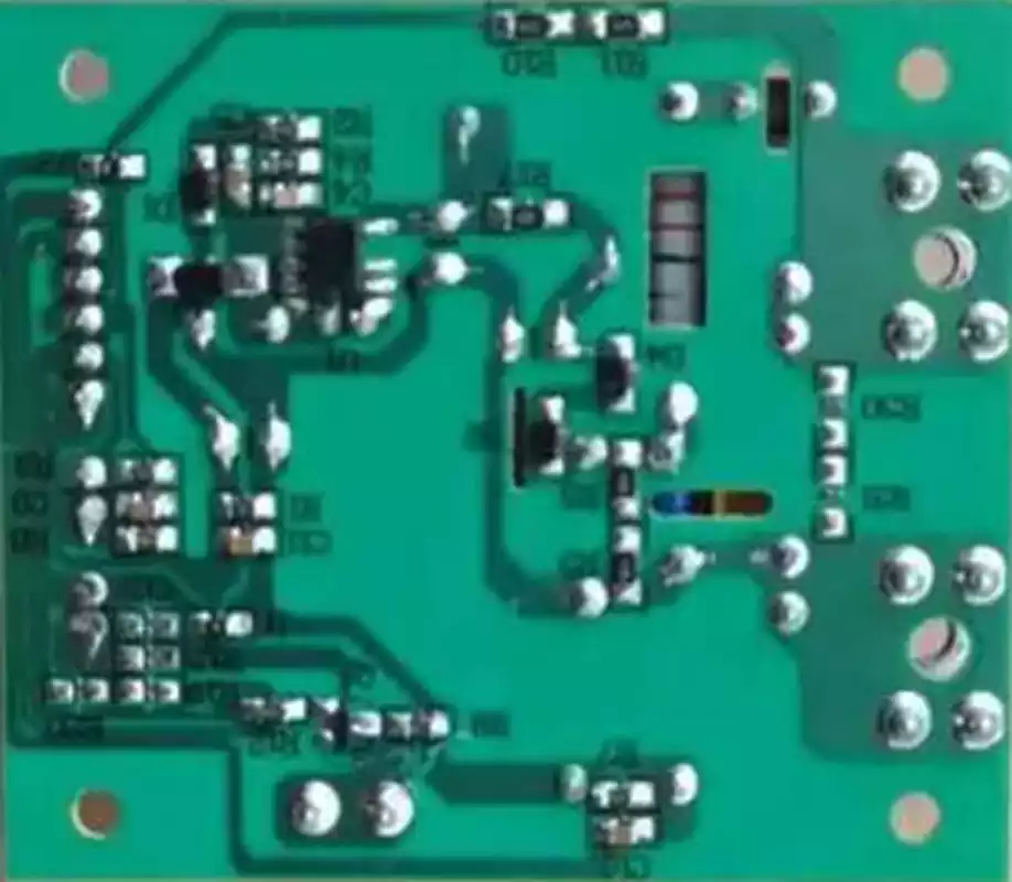
GLX PCB rite board is a primary replacement circuit board specifically engineered for Hayward Goldline AquaRite salt chlorinator systems. It serves as the system’s central control unit, overseeing all core functions including salt chlorine generation, flow monitoring, and system status display.
The glx PCB rite board is the central control unit of the Hayward AquaRite salt chlorination system. You may consider it the brain or central nervous system of the entire system, precisely coordinating and managing the operation of every component to ensure your pool water remains safe and clean. Without this circuit board, the salt chlorination system cannot function.
Its primary functions encompass every aspect of the system. Firstly, it regulates the electrical current delivered to the electrolytic cell (salt cell), thereby controlling chlorine production to meet the demands of varying pool sizes and usage patterns. Secondly, it monitors water flow and temperature by connecting to flow switches and temperature sensors, ensuring the system operates only under safe and effective conditions. Furthermore, this circuit board powers the LCD display on the control panel, providing users with system status updates, salt concentration readings, and any potential error codes, facilitating human-machine interaction.
How to diagnose AquaRite circuit board faults?
Accurate fault diagnosis is paramount before purchasing a new GLX PCB rite board,preventing unnecessary expenditure of time and money. Symptoms of circuit board failure can sometimes mimic issues with other components, such as the electrolytic cell or sensors, necessitating systematic troubleshooting. A common problem arises when the board’s contacts wear down or overheat over time, potentially causing system malfunction.
Common symptoms indicating potential circuit board failure include:
Complete power failure: No display on the control panel, with all indicator lights off.
No chlorine generation: Despite correct settings and normal salt concentration, the ‘Generating Chlorine’ indicator remains off or flashes, with no actual chlorine production occurring.
Display malfunction: LCD screen displays garbled text, missing characters, or remains blank.
Error code display: Specific error codes appear on the panel, such as ‘FLO’ (flow issue) or ‘PCB’ (circuit board fault), which cannot be cleared through standard methods.
Button unresponsiveness: Pressing buttons on the control panel elicits no system response.
GLX PCB RITE Board Replacement Step-by-Step Guide
Replacing the main circuit board in an AquaRite system is a precise task, but one that can be undertaken by users with basic DIY skills provided the correct steps are followed. Before commencing, ensure all power to the control box is disconnected, including circuit breakers, to guarantee absolute safety. Whilst not complex, the replacement process requires careful attention and patience.
Safety Preparation: Double-check that all circuit breakers supplying power to the pool equipment area are switched off. Use a voltage tester to confirm the control box is de-energised.
Open the Control Box: Unscrew the fasteners securing the Hayward AquaRite control box cover, remove the lid, and expose the old circuit board inside.
Photographic Documentation: Before disconnecting any connections, photograph the wiring layout of the old circuit board from multiple angles using your mobile phone. This photograph will serve as a crucial reference when installing the new board, ensuring each wire is reconnected to its correct position.
Disconnecting Connectors: Carefully unplug all wire connectors from the old circuit board. These connectors typically feature clips that require gentle pressing to release. Avoid pulling on the wires forcefully to prevent damage.
Remove the old circuit board: Unscrew the fasteners securing the old circuit board. Typically, four to six screws are positioned at the corners and edges of the board. Once removed, carefully lift the old board out of the control box.
Install the new circuit board: Position the new glx PCB rite board inside the control box, aligning it with the screw holes. Secure it using the screws previously removed. Ensure the board sits flat and is firmly fixed.
Reconnect wiring: Referring to your previously taken photographs, plug all wire connectors back into their corresponding sockets on the new circuit board. Each connector’s size and shape is usually unique to prevent incorrect insertion.
Close the control box and restore power: Carefully inspect all connections for security and correctness. Replace the control box cover and tighten the screws. Then, switch the circuit breaker back on to restore power to the system.
Initial setup and testing: Once powered, the new circuit board display may illuminate. You may need to reconfigure basic settings per the manual, such as time and cell model. Subsequently, activate the pump to observe whether the system operates correctly and commences chlorine production.
The glx PCB rite board, as the core component of the Hayward AquaRite salt chlorination system, is critical to maintaining pool water quality. Mastering troubleshooting methods enables prompt response to issues; understanding replacement procedures empowers users to resolve problems independently.