LED lighting products’ efficiency, energy-saving properties and extended lifespan have driven their increasing market prevalence. At the core of these products, LED light pcb design is pivotal in ensuring luminaire performance, thermal management and reliability. This article delves into each stage of the LED PCB design process to assist you in creating an outstanding LED PCB design solution.
LED Light PCB Design Process
The schematic diagram initiates the LED light pcb design process. Following its completion, proceed with subsequent steps such as component layout and parameter configuration. PCB routing constitutes a critical consideration. This may prove challenging without prior experience in LED circuit board routing.
LED Light PCB Parameter Configuration
Several factors must be considered during LED light PCB design, including driver type, power supply, board dimensions, and spacing between adjacent wires. Drivers come in two types: constant current (CC) and constant voltage (CV). Your choice depends on the LED type used. The datasheet will specify the correct settings. Once the appropriate driver type is determined, LED lighting design can commence.
LED PCB Component Layout
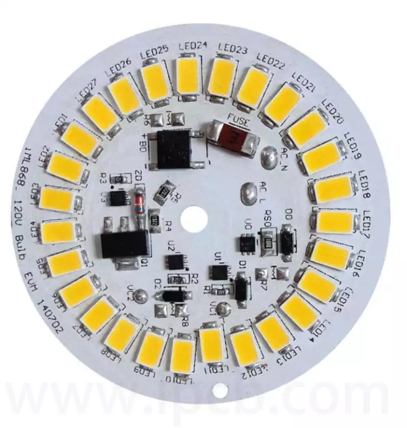
If you are considering designing LED-powered products, understanding the components that make up a typical PCB can be beneficial. These components include LEDs, circuitry, and various other elements. These components typically take the form of tiny ‘chips’ or cylinders. As with any other circuit board, they should be positioned on the board so as not to obstruct the solder pads. They will be located behind the plated-through hole components.
PCBs incorporating LEDs are usually fabricated from multi-layer FR-4 substrates. Given that LEDs generate significant heat, designing the circuit board to accommodate this thermal load is crucial. Furthermore, LED PCB boards should allow sufficient clearance between metal, pads, and traces. Appropriate component tolerances can also minimise board errors. Finally, when undertaking LED light PCB design, carefully consider the substrate material, as this will determine the LED’s thermal conductivity.
LED Circuit Board Wiring
LED circuit board wiring is relatively straightforward, but note the lead length for each component in your LED light PCB design. Typically, the cathode lead is shortest and connects to the same socket as the anode. Resistors follow this principle, connecting to the socket matching their anode. The other wire should likewise be red or black.
For LED circuit board wiring, bear in mind the following LED light PCB design guidelines.
Prior to LED PCB board design, select LED components according to your LED light pcb design requirements.
Plan the LED PCB wiring layout and verify its correctness before commencing connection of the LED board.
Ensure all LED components present in the LED light PCB design are properly grounded on the circuit board.
Employ appropriate wire gauge for each section of the LED PCB according to current load.
Clamp any wires crossing other conductive paths to prevent interference or contact with other components.
Heat-shrink any exposed wire joints as an additional measure against interference or short circuits.
Upon completing the LED light PCB design, verify continuity between all points throughout the circuit before energising.
When connecting external power supply voltage to the LED PCB board in the design, always use an approved power source.
Before energising, confirm there are no short circuits, open circuits, reverse polarity, or component placement errors.
Regur varlarly test the LEDs to ensure optimal performance undeying operating conditions. Correct routing in the led light pcb design is critical for LED operation.