The flight control board is the core control unit of a drone, responsible for attitude calculation, sensor fusion and the execution of flight algorithms. Its PCB primarily carries high-speed signals, placing extremely high demands on impedance control, signal integrity and EMI/EMC performance; it typically employs an HDI structure and micro-blind via design to achieve a high-density, compact layout.
Core Components of a Flight Controller Board
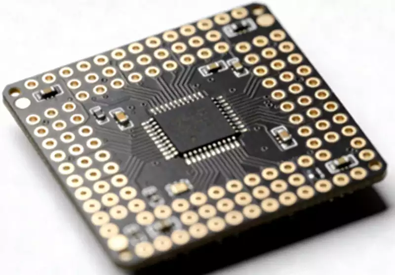
1.Main Control Chip: The ‘brain’ of the flight control board, responsible for running flight control algorithms, processing sensor data, interpreting remote controller commands, and outputting motor drive signals. The mainstream solution is the ARM Cortex-M series (such as the STM32), whilst high-end flight control boards utilise more powerful SoC chips to meet the demands of complex scenarios such as autonomous route planning and multi-sensor fusion. The soldering precision and thermal management design of the main control chip directly impact computational stability and are key control points in PCB manufacturing.
2.Inertial Measurement Unit (IMU): The “sensory organ” of the flight control board, comprising a gyroscope, accelerometer and magnetometer; some high-end models also integrate a barometer. The gyroscope measures angular velocity along three axes, the accelerometer measures linear acceleration, the magnetometer acts as an electronic compass, and the barometer is used to estimate altitude. The IMU is extremely sensitive to vibration and electromagnetic interference. In PCB layout, it must be positioned at the centre of the flight control board, away from sources of interference such as motors and power supplies, and supported by vibration-damping design. This places high demands on PCB layout precision and manufacturing processes.
3.Power Management Module: The ‘energy hub’ of the flight control board, which steps down and regulates the battery voltage (e.g., 11.1V lithium battery) to the voltages required by various components (3.3V, 5V, etc.), whilst providing filtering and protection. A two-tier architecture of ‘main power supply + local LDO’ is adopted: the DC-DC module converts high voltage to medium voltage, which is then supplied to analogue circuits such as the IMU via a low-noise LDO. During PCB manufacturing, the power plane and ground plane must be carefully planned, and the copper thickness along high-current paths must be increased.
4.Interface Circuits: The “communication bridge” of the flight control board, including receiver interfaces, ESC interfaces, serial ports/UART (for connecting to GPS and data radios), and USB (for firmware flashing and debugging). PCB design must prioritise signal integrity; high-speed signals should utilise equal-length traces, avoid right-angle turns, and keep critical signals away from interference sources.
Furthermore, the flight control board integrates auxiliary components such as indicator LEDs, filter capacitors and TVS diodes for status indication, power filtering and surge protection. These components collectively form a complete functional system, placing higher demands on PCB layout density and manufacturing precision.
Core Functions of the Flight Control Board
1.Sensing Functions: These are performed collaboratively by sensors such as the IMU, GPS and barometer, which collect real-time data on attitude, position, velocity and altitude, and transmit it to the main control chip. For example, when a drone tilts due to air turbulence, the gyroscope detects changes in angular velocity and the accelerometer measures the tilt angle; this data is transmitted at high speed via the PCB circuitry to the main control chip. This process requires extremely low transmission latency and precise impedance control.
2.Decision-making function: The main control chip runs algorithms such as PID control and Kalman filtering. By combining sensor data with remote control commands, it calculates optimal control commands to adjust motor speed or servo angle. For example, in hover mode, if there is a deviation in altitude, the main control chip adjusts motor speed based on barometer data; during autonomous flight, it plans the optimal path using GPS data. This function requires the main control chip to be highly compatible with the PCB circuitry, and the thermal management design must be adequate to prevent performance degradation caused by overheating.
3.Execution Function: Control signals output by the main control chip are transmitted via the PCB circuitry to the ESC interfaces, driving the motors to adjust flight attitude and speed; drones equipped with a gimbal also use servo interfaces to control the gimbal and stabilise the camera. This process requires the PCB interface circuitry to possess good drive capability and reliable circuit connections.
4.Safety Protection Functions: These include low-voltage protection (automatic return-to-home or emergency landing), loss-of-control protection (automatic return-to-home upon signal loss), geofencing, and abnormal attitude protection. The implementation of these functions relies on the coordinated operation of various modules on the flight control board, requiring the PCB to transmit signals stably even under extreme conditions.
Core Requirements for Flight Control Board PCB Manufacturing
1.High Precision: Flight control boards feature high circuit density, with line widths/spacing typically ranging from 0.15 to 0.2 mm, and high-end products reaching below 0.1 mm. This requires high etching precision with minimal side etching, and line width tolerances controlled within ±8%; laser-drilled holes must have a diameter ≤0.15 mm, with smooth, burr-free walls and uniform copper plating to prevent copper voids or cold solder joints within the holes.
2.Anti-interference Design: Flight control boards house both digital circuits (main control chips, interface circuits) and analogue circuits (IMU, barometer) in the same space. Electromagnetic interference from digital circuits can easily affect the accuracy of analogue measurements. Therefore, a layout with separate digital and analogue zones is required, with power and ground lines planned independently; the digital ground and analogue ground are connected via a single point using ferrite beads or 0Ω resistors. Pad spaces for a shielding cover are reserved on the PCB surface, and critical areas are surrounded by a ground plane to enhance electromagnetic compatibility and meet CE/FCC certification requirements.
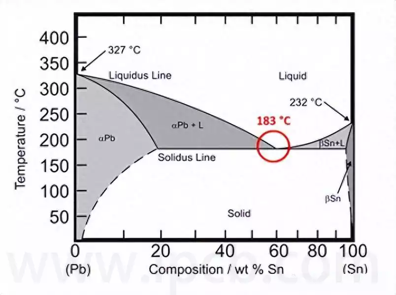
3.Vibration Resistance and Reliability: High-frequency vibrations during drone flight may cause components to detach or solder joints to crack. High-reliability board materials (such as FR4) must be selected, with pad designs adapted to the vibrating environment, and lead-free soldering processes adopted to enhance solder joint strength. The PCB surface is coated with conformal coating to provide protection against moisture, dust and corrosion; copper heat spreaders and thermally conductive vias are installed around power devices to prevent damage from overheating.
4.Manufacturability and Consistency: Mass production requires consistent performance across every PCB; therefore, comprehensive quality control must be established to monitor parameters such as line width, via diameter, plating thickness and insulation resistance. The design must adhere to DFM rules, such as maintaining a minimum spacing of ≥0.3mm between vias and pads, and a minimum BGA escape line width of ≥6mil, to prevent issues such as solder leakage in dense via clusters and poor soldering, thereby improving production efficiency and yield rates.
Applications of Flight Control Boards
Consumer-grade drones (aerial photography, FPV racing): Emphasis on miniaturisation, low cost and ease of debugging. PCBs are typically 4–6 layers with line widths/spacing ≥0.15mm, meeting basic flight control requirements whilst prioritising cost-effectiveness and mass-producibility.
Industrial grade drones (agricultural crop protection, power line inspection, surveying): Emphasis on high reliability, anti-interference capabilities and long endurance. PCBs are typically 6–10 layers, with high-end models reaching 12 layers; trace widths/spacing are as low as 0.1 mm. They support complex functions such as multi-sensor integration, autonomous route planning and resume-from-breakpoint flight, requiring high-precision processes alongside optimised thermal management and anti-interference design.
Military drones: These require extreme environmental adaptability (wide temperature range of -40°C to 85°C), shock resistance and radiation resistance. PCBs typically consist of 10 or more layers, utilising military-grade materials and manufacturing processes, representing the pinnacle of PCB manufacturing technology.
As drones evolve towards miniaturisation, higher speeds and greater intelligence, the integration of flight control boards will continue to increase, with circuit precision breaking through the 0.08 mm barrier and the number of PCB layers rising further. Concurrently, demands for lightweight construction, low power consumption and environmental sustainability are constantly increasing. This necessitates the PCB manufacturing industry to continually overcome technical bottlenecks, enhance production capacity for high-precision, high-density PCBs, and promote the application of green processes such as cyanide-free copper plating and resin-filled vias, thereby providing robust support for the upgrading of flight control boards.