Connections between pcb circuit boards are primarily achieved through conductive connectors, wires, flexible printed circuits (FPC), board-to-board connectors, and soldering techniques. Among these, flexible printed circuits (FPC) serve as a widely adopted connection method, excelling in the creation of reliable, high-density electronic products. Their lightweight, thin profile and excellent flexibility make them highly suitable for space-constrained applications or scenarios requiring dynamic bending of circuit connections. Flexible circuits not only effectively conserve space and reduce weight but also enhance the reliability and durability of electronic devices.
Types of PCB Connections
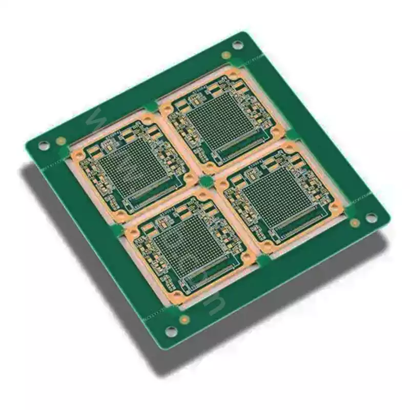
Interconnection between chips and PCB circuit boards
The challenge with chip-to-PCB interconnections lies in excessive density, where the fundamental structure of PCB materials becomes the limiting factor for further density increases. The solution involves utilising on-chip local wireless transmitters to transmit data to adjacent circuit boards.
Internal Interconnections Interconnections within a PCB circuit boards must adhere to these principles: employ high-performance PCBs with controlled dielectric constants by layer to manage electromagnetic fields. Avoid components with leads and refrain from using via-through processes on sensitive boards, as these introduce lead inductance at the vias. Select non-electrolytic nickel plating or immersion gold processes to provide superior skin effect for high-frequency currents.
External Connections
External connections primarily comprise the following types:
- Wire Soldering
Directly solder wires between external connection points on the PCB circuit boards and external components or parts without requiring connectors. - Ribbon Cable Soldering
This method is commonly used for 90-degree angle connections between two PCB circuit boards, forming an integrated PCB assembly. - PCB sockets: This method is frequently employed in complex instrumentation. A printed connector is fabricated from the PCB edge, designed to match a dedicated PCB socket in terms of dimensions, contact count, contact spacing, and locating hole positions.
- Standard pin connections
This method suits small instruments, connecting two PCBs via standard pins. The boards are typically arranged parallel or perpendicular to each other.
Electrical Connectors
Electrical connectors serve as fundamental components for establishing connections between pcb circuit boards. Employing a plug-and-play mechanism, they enable rapid circuit engagement and disengagement without requiring soldering operations, thereby providing electrical interconnections for circuit boards. Connectors are available in diverse designs to accommodate varying current and voltage requirements, and can be customised according to specific PCB layouts.
Key considerations when selecting connectors include: current and voltage carrying capacity, impedance matching, insertion/removal cycles, and environmental conditions. Manufacturers typically provide detailed specification sheets for their connector products, covering both electrical and mechanical performance aspects.
Wire Connections
In certain applications, wires are employed to interconnect pcb circuit boards. This method offers a straightforward and flexible approach for linking different PCBs. Through soldering or the use of terminals and terminals, wires connect specific points on one circuit board to corresponding points on another. This connection method is typically suitable for high-current transmission or scenarios requiring customised wiring.
The wire connection process generally involves stripping, soldering, and insulation treatment. To ensure connection reliability, solder joints require stringent process control, while insulation treatment effectively prevents short circuits.
Flexible Printed Circuit (FPC)
Flexible Printed Circuit (FPC) interconnections represent a specialised connection method.Owing to their inherent flexibility, they are particularly suited for electronic devices with constrained space or requiring curved layouts.Flexible circuits reduce the volume and weight of connections while delivering outstanding durability and reliability.
Key design considerations for FPCs include: trace spacing, bending radius, material selection, and conductor layer thickness. Utilising flexible circuits not only shortens overall design cycles but also simplifies PCB assembly processes.
Multilayer Printed Circuit Boards (PCBs)
A multilayer printed circuit board (PCB) consists of conductive layers laminated between multiple insulating layers. Its primary connection methods include:
- Via connections: Vias represent the most common interconnection method in multilayer PCB circuit boards. Given the multiple layers, designers create small holes between layers, which are then filled with plating or other conductive materials to establish electrical connections. Common types include blind vias (connecting inner and outer layers only), buried vias (connecting inner layers only), and through-holes (penetrating all layers).
- Microvia: With advances in PCB manufacturing technology, microvias are extensively employed in high-density interconnect (HDI) circuit boards. These smaller vias support higher circuit densities and are typically created using laser drilling techniques.
- Conductive Adhesive Bonding: In certain specialised applications, conductive adhesives may be employed to connect distinct circuit layers. This method is suitable for scenarios with specific requirements beyond conventional conductive techniques.
- Surface Mount Technology (SMT): Within multilayer PCBs, surface mount technology effectively reduces required interconnect lengths, enhancing signal integrity. Through strategic layout, interlayer connection demands can be minimised, thereby improving overall circuit performance.
- Stacked Vias: In high-performance designs, stacked vias employ two or more microvias layered together. Through specific design rules, this achieves higher connection density and lower electrical impedance.
Board-to-Board Connectors
Board-to-board connectors represent another high-density interconnection solution. These connectors enable direct vertical or horizontal interconnection of multiple circuit boards without wires or cables. Typically comprising female and male ends, they provide stable and repeatable electrical connections.
When employing board-to-board connectors, selecting the appropriate type is essential to match the PCB design and required electrical performance. This involves considering contact count, pitch, and arrangement to ensure optimal signal integrity and reliability within constrained spaces.
Soldering Techniques
Soldering represents a traditional and highly reliable method for permanently joining components or connection points on pcb circuit boards. It provides robust physical and electrical bonds, proving particularly suitable for applications requiring resistance to significant mechanical stress or operation in high-temperature environments.
Soldering techniques encompass various approaches, including wave soldering, reflow soldering, and manual soldering. Each method possesses distinct advantages and limitations for specific applications. Consequently, selecting the appropriate technique requires a balanced consideration of production efficiency, cost, and the required level of connection reliability.
Establishing connections between PCB circuit boards necessitates comprehensive consideration of design requirements, environmental conditions, and cost factors. Whether employing flexible circuit boards, conductive connectors, or soldering techniques, the critical imperative remains ensuring connection reliability and efficiency. This guarantees that interconnected circuit boards maintain high performance and long-term stability.