PCB Impedance Calculator is a software tool for calculating the impedance of transmission lines on PCBs. By using it, engineers can quickly and accurately predict and optimize the impedance performance of a PCB to ensure reliable signal transmission.
PCB Impedance is the ratio of voltage to current in a circuit and is used to measure how well a circuit impedes a signal. In a circuit board, PCB impedance manifests as the combined effect of resistance, inductance, and capacitance between components on the PCB board. The impedance magnitude directly affects signal transmission quality and energy loss.
Factors affecting the PCB impedance
Resistance: The resistance of a conductor is directly proportional to the length of the conductor and inversely proportional to the cross-sectional area of the conductor. In printed circuit boards, the length and width of the conductor have a significant effect on resistance.
Inductance: When the current changes, a magnetic field is generated around the conductor, which will resist the current. In printed circuit boards, the length and number of turns of the wire affect the inductance.
Capacitance: An electric field exists between two conductors, and the ability of a capacitor to hold a charge is related to its capacitance when the potential difference is certain. In the printed circuit board, the distance between the wires and the relative position of the capacitance has an impact.
Dielectric: The dielectric of a printed circuit board also has an important effect on impedance. The relative dielectric constant and loss angle tangent of the dielectric affects the magnitude of capacitance and inductance.
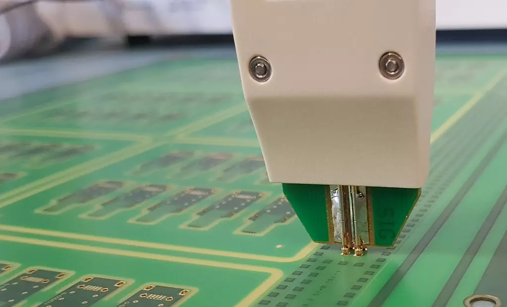
Calculation formula for pcb impedance
The impedance calculation of printed circuit boards needs to consider the combined effect of resistance, inductance, and capacitance. Commonly used calculation formula: Z = R + j (ωL-1/ωC)
Among them:
Z for the impedance, the unit is ohms (Ω).
R is the resistance in ohms.
ω is the angular frequency in radians/second (rad / s).
L is the inductance in Henrys (H).
C is the capacitance in Farads (F).
j is the imaginary unit, indicating a 90° phase angle.
Parameter explanation and calculation method
Resistance (R): Resistance is the obstruction of current by a conductor and is determined by the material, length and cross-sectional area of the conductor. In PCB, the resistance of a wire can be calculated by the following formula:
R=ρ×(L/A)
where:
ρ is the resistivity of the conductor in Ω-m.
L is the length of the wire, in m.
A is the cross-sectional area of the wire, the unit is m².
Inductance (L): Inductance is the coil of the current changes in the obstruction. In PCBs, the inductance of a wire is related to the length, the number of turns and the distance between the wires. Usually, PCB manufacturers provide inductance values for standard line widths and spacing. If customized line width and spacing is required, it can be calculated by simulation with relevant software tools.
Capacitance (C): Capacitance is the ability of an electric field to store an electric charge. In a PCB board, the capacitance between wires is related to the distance and relative position between them. The formula for capacitance is as follows:
C=ε0×εr×(S/d)
where:
ε0 is the vacuum capacitance, with a value of 8.854 × 10-¹² F/m.
εr is the relative capacitance rate, related to the PCB sheet.
S is the distance between the two wires, in m.
d is the wire diameter or spacing in m.
Angular Frequency (ω): Angular frequency is a physical quantity that describes the frequency of a simple harmonic vibration or fluctuation, and is related to the period T and frequency f as:
ω = 2πf = 2π/T
where:
f is the frequency in Hz.
T is the period in s.
PCB Impedance Matching and Signal Integrity
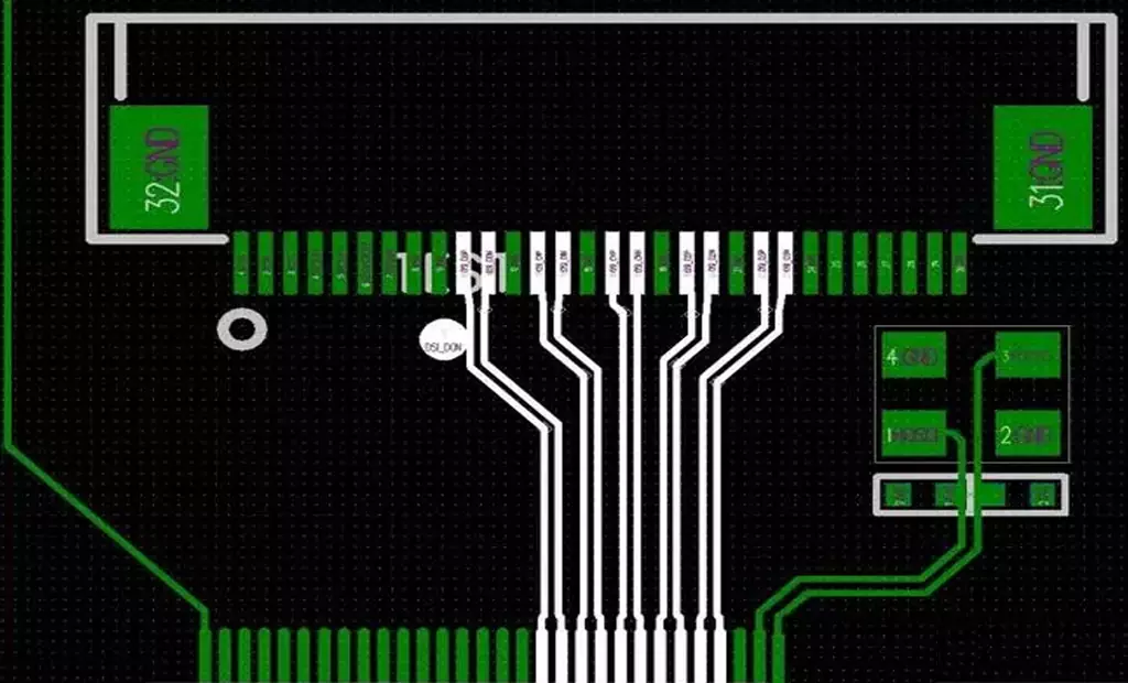
PCB Impedance matching is critical in the transmission of high-speed digital signals. When the PCB impedance of the source and the load are perfectly matched, the signal can be transmitted without loss. To achieve PCB impedance matching, the wiring of the printed circuit board needs to be carefully designed, such as selecting the appropriate line width, line spacing, size, and other parameters. Signal integrity (SI) issues such as signal reflection, crosstalk, and propagation delays also need to be considered. Evaluating and optimizing the SI performance utilizing simulation and testing is one of the hotspots in current research.
Advantages of PCB impedance calculator
Fast and Accurate: The PCB impedance calculator is based on a precise mathematical model and can quickly and accurately calculate PCB impedance value, avoiding the errors and tediousness of manual calculations.
Adjustable Parameters: The PCB impedance calculator provides a series of adjustable parameters, such as the width, thickness, material, and spacing of the wires, allowing users to customize the calculations according to their actual needs.
Predictive capability: With the PCB Impedance Calculator, engineers can predict the impact of different process parameters on PCB impedance, thereby identifying and solving potential problems in advance and improving the reliability and performance of the design.
Material Selection: The PCB impedance calculator can compare the performance of different materials and media to help engineers select the most suitable PCB materials, reducing costs and risks.
But it also has some disadvantages
Dependency: requires users to input some parameters and data, if these data are inaccurate or incomplete, it will lead to inaccurate calculation results.
Technical requirements: requires some technical knowledge and experience to use correctly, for beginners may have some learning difficulties.
Limitations: provides a certain range of reference values and cannot completely replace the actual test and measurement. Therefore, in the actual application, it is still necessary to carry out actual testing and verification.
PCB impedance calculator plays an PCB important role in PCB design. Through the use of PCB impedance calculator, engineers can quickly and accurately predict and optimize the PCB impedance performance, thereby improving the reliability and performance of electronic equipment.
