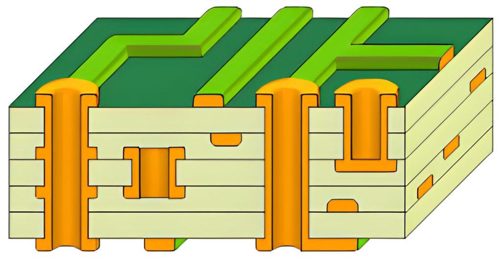
Isolated circuits are circuits with different functions or signal paths that are separated on a printed circuit board by a specific design and layout to avoid interfering or affecting each other. The implementation of this isolation technique can significantly improve the reliability and stability of the circuit board and reduce failures or performance degradation due to circuit interference.
While isolation is an important part of isolation design, it is not simply a design electronic component. From determining the level of isolation required, to providing isolated power supplies to aid in isolating data paths, to making the solution fit the available space – there are many design tradeoffs that need to be evaluated. However, each new project has its own unique design goals and design requirements. A variety of factors, including technical difficulty, similarity to previous designs, timing, and resource allocation, combine to determine how much of the design can be reused and how many entirely new design options are required. Reusing a previous design or architectural approach with minimal changes often reduces risk and speeds implementation. However, new features or increased levels of performance often dictate the need to investigate new approaches. It is also important to spend scarce development resources on evaluating new and improved technologies to increase the technical value of the design.
The main purpose of circuit isolation is to cut off the path of noise interference by isolating components, thus achieving the effect of suppressing noise interference and making electrical and electronic equipment comply with the requirements of electromagnetic compatibility. Circuit isolation: isolation of analog circuits, isolation of digital circuits, digital circuits and analog circuits between the isolation. The isolation methods used are: transformer isolation, pulse transformer isolation, relay isolation, opto-coupler isolation, DC voltage isolation, linear isolation amplifier isolation, fiber optic isolation, A/D converter isolation method.
To say intuitively that is, if the product is used in a more complex environment (such as industrial environments), or involves a number of different power supply system before the mutual communication (such as RS232, RS485, CAN and other communication interfaces) are required (or even necessary) isolation.
Isolation in electronic circuits will involve three aspects of isolation:
The first is the isolation of the power supply, usually choose DC-DC isolation power module.
The second is the isolation of signals and data.
The third is the isolation of the ground, the isolation of the front side of the ground (GND) and the back side of the ground (GNDISO) can not be connected together, but some have to be connected together on the occasion, we can choose to use a magnetic bead or 0 ohm resistor placed between the two ground.
The isolation technique when reading signals on the PCB board ensures that the transmission of digital or analog signals between the transmitter and receiver side is not interfered by barriers. This technique makes it possible to prevent damage to signals caused by loop currents arising from different ground potentials, even if the difference in ground or reference levels between the transmitter and receiver sides is as high as several thousand volts. Its main application scenarios include:
When the system noise level is high, which may adversely affect the signal quality, the isolation technology can separate the signal subsystem from the grounding and power supply parts, thus ensuring the stability and reliability of the signal isolation part and meeting the stringent requirements of system design.
When the system voltage varies greatly, such as in a strong circuit, the isolation technology can convert the working voltage to the working range allowed by the IC, thus protecting the circuit components from the damage of high voltage.
When the electrical connection between the reference levels may generate a current path that poses a safety hazard to the operator, the isolation technology can effectively limit the current to a safe range to protect the safety of the operator.
In the practical application of isolation technology, designers need to carefully select suitable isolation devices according to different isolation signal types and isolation requirements. These devices mainly include:
The first type of isolation devices, which rely on optical transmitters and receivers to traverse the isolation barrier. Major optical isolation devices include optocouplers and isolated transceiver ICs.These devices utilize light to distribute system currents and capacitance to avoid electrical interference, and are particularly suited to the isolation of digital signals.
Analog transformers, which send and receive signals by electromagnetic induction. Although transformers are difficult to produce, difficult to control parameters precisely, and not easy to manufacture as ICS, and are not very convenient to use, the problem of linearizing analog signals makes transformer isolation a necessary option.
Printed circuit board isolation circuits play an indispensable role in circuit design and manufacturing as a key technology to ensure the stable operation of electronic equipment. Through careful design and layout, isolation circuits can effectively separate circuits with different functions or signal paths to avoid mutual interference, thus improving the reliability and stability of the circuit board.