Rogers RO4350B dielectric constant stability is relatively high, the standard value using 10GHz frequency test value of 3.48, with the frequency increase in dielectric constant will decline, 24GHz frequency dielectric constant compared to the 10GHz frequency decreased by 0.01, for 3.47.
Rogers RO4350B high-frequency board is fully compatible with traditional PCB manufacturing technology, do not need to do through-hole copper-plated special pre-treatment (PTFE plates need to do plasma treatment) or other pre-treatment process, solder resist process can also be ground plate. Compared with traditional microwave material laminates are less expensive, so they are widely used in active devices and high power RF designs requiring fire rating UL 94V-0.
Rogers RO4350B plates have the following characteristics:
- Low RF loss: Df:0.0037 10GHz;
- Low dielectric constant: Dk:3.48+/-0.05 and fluctuation with temperature;
- Low Z-axis coefficient of thermal expansion: 32 ppm/°C;
- Low coefficient of in-plate expansion;
- Low dielectric constant tolerance;
- Excellent dimensional stability;
- Stable electrical characteristics at different frequencies;
- Processing similar to FR-4, and easy to mass production and multi-layer mixing and pressing of FR4, so it has a great price competitive advantage.
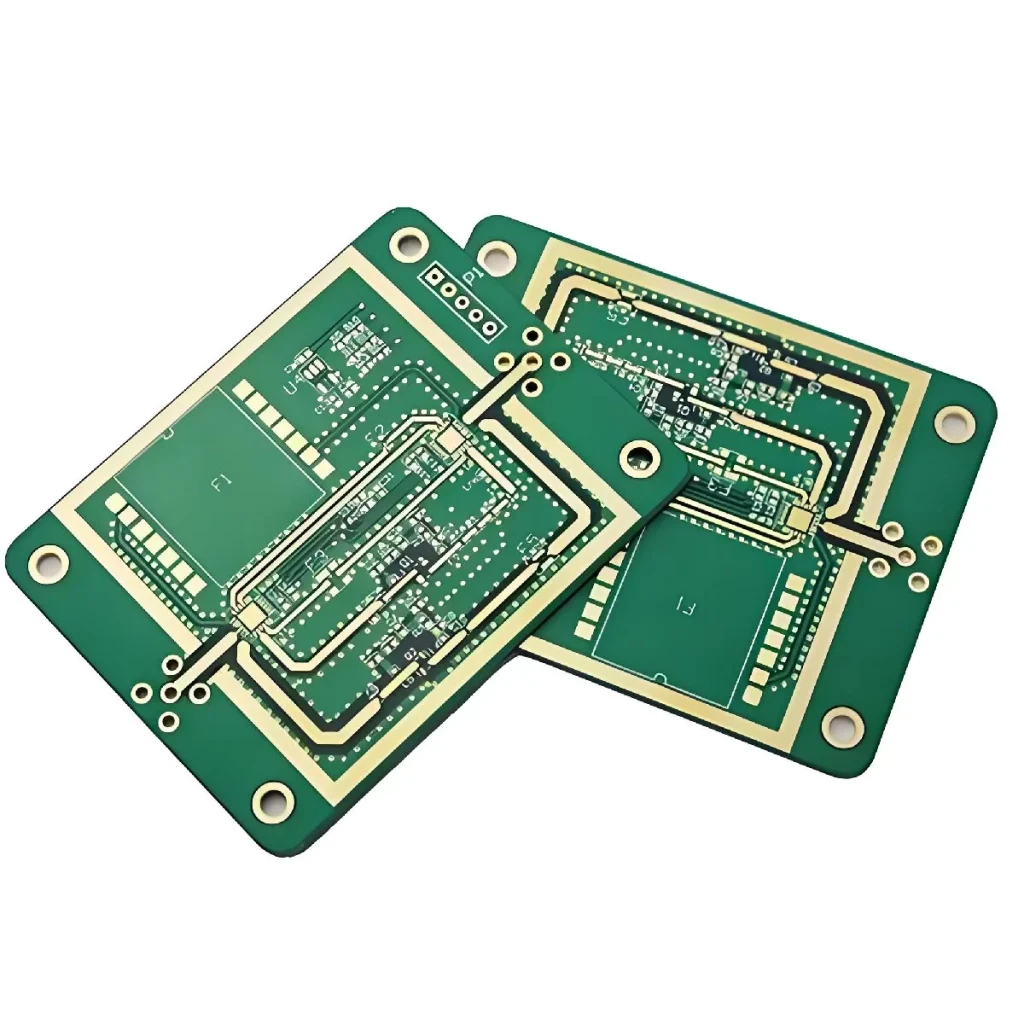
RO4350B, as a low-loss hydrocarbon resin and ceramic filler laminate and semi-cured sheet material, not only has excellent performance, but is also suitable for use in high-frequency applications up to 30 GHz. Its line processing costs are relatively low due to the standard epoxy resin/glass fibre (FR-4) manufacturing process. As a result, Rogers’ RO4350B high-frequency boards offer an ideal balance of cost and performance, making them a very high-quality choice. In order to better meet the design requirements, this paper investigates the insertion loss of microstrip transmission lines based on RO4350B material at 24 GHz frequency when designing microstrip array antennas.
The insertion loss of microstrip line mainly includes conductor loss, dielectric loss, surface wave loss and radiation loss, in which conductor loss and dielectric loss occupy the main position. Due to the skin effect, the distribution of high-frequency current on the microstrip line is concentrated in the thin layer of the conductor tape and the ground plane in contact with the dielectric substrate, resulting in a much higher equivalent AC resistance than that at low frequencies. The conductor loss is significantly greater than the dielectric loss at operating frequencies below 10 GHz, while the dielectric loss exceeds the conductor loss as the frequency rises to 24 GHz.
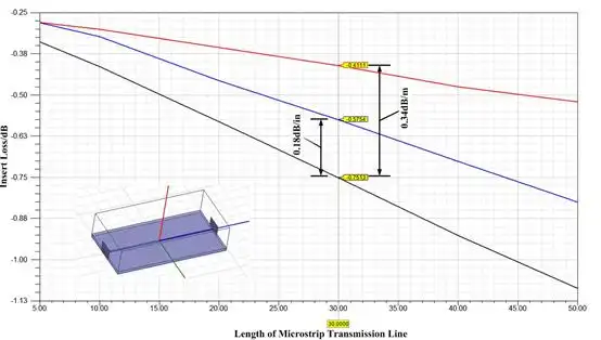
Figure 1 shows the results of the HFSS calculations of the insertion loss of microstrip lines of different lengths on a Rogers RO4350B HF board with a thickness of 20 mil. As can be seen from the figure, the microstrip line insertion loss is about 17 dB/m, of which the metal loss is 4.47 dB/m, the dielectric loss is 11.27 dB/m, and the other losses are 1.26 dB/m. In comparison, Table 1 shows the microstrip line insertion loss data computed by MWI2016, which resulted in 24.4 dB, with the dielectric loss close to that of the HFSS results, and the conductor loss being about 7 dB higher. The difference is mainly due to the fact that the HFSS model does not take into account the effect of the surface roughness of the conductor and ground plane. The following figure shows the microstrip line insertion loss calculated by HFSS.
Strategies for Reducing Microstrip Line Insertion Losses
1.Carefully select the thickness of the HF circuit board and carefully use green oil
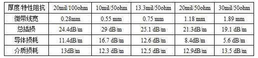
By observing the data in Table 1, we can find that under the condition of the same characteristic impedance, the conductor loss of the microstrip line will show a decreasing trend with the increase of the dielectric thickness, while the dielectric loss remains basically stable. The reason behind this is that as the thickness of the dielectric substrate increases, the width of the microstrip line becomes narrower accordingly, resulting in a higher concentration of high-frequency current, which in turn increases the conductor loss.
In addition, it should be noted that at 24 GHz, the loss tangent angle of the green oil dielectric is larger, which leads to a further increase in the insertion loss of the microstrip line. Therefore, when designing a microstrip antenna at 24 GHz, we need to perform solder resist windowing on the antenna area to reduce the adverse effect of green oil on the insertion loss of the microstrip line.
In order to show the microstrip line insertion loss more intuitively, we have attached a graph of the calculation results from the MWI2016 software. This graph will help us better understand the trend of microstrip line insertion loss and provide a useful reference for optimising the microstrip line design.
2.Prefer LoPro Copper Foil
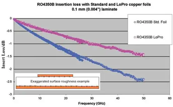
Conductor and Ground Plate Copper foil surface roughness is also an important factor affecting the insertion loss of microstrip lines. The smoother the surface of the copper foil, the lower the conductor loss. RO4350B provides two types of copper cladding, electrolysable copper foil (ED) and low roughness inversion processed copper foil (LoPro), of which the surface roughness of the ED copper foil is around 3um, while the LoPro copper foil can reach 0.4um, so it can effectively reduce the conductor loss. Figure 2 shows the microstrip line insertion loss comparison of these two types of copper cladding with dielectric substrate thickness of 0.1 mm. It can be seen from the figure that the insertion loss of microstrip line of LoPro copper cladding is 40% smaller than that of ED copper cladding at 24 GHz. The insertion loss comparison of electrolytic copper and inverted copper is shown below:
3.Reasonable choice of surface treatment process
Surface treatment process is also one of the factors affecting conductor loss. There are four common surface treatment processes, which are divided into immersion silver, immersion gold (no nickel gold), nickel gold (nickel 3-5um, gold 2.54-7.62um) and immersion tin. Table 2 gives the electrical parameters of these metals, of which nickel is a ferromagnetic material, its magnetic permittivity of 600, according to the skinning depth formula, the skinning depth of nickel is one order of magnitude smaller than that of other metals, so the surface resistance of nickel is dozens of times greater than that of other metals, resulting in nickel-gold process of the conductor loss is much greater than that of other processes. Figure 3 compares the insertion loss of bare copper, immersed silver and nickel-gold surface treatment processes, with a substrate thickness of 20 mil. As can be seen in the figure, the insertion loss of immersed silver and bare copper is about the same, but the insertion loss of the nickel-gold surface-treated microstrip line is 4 dB/m (10 GHz) larger, and it can be predicted that this difference will be even larger at 24 GHz. The conductivity, magnetic permittivity and skinning depth of the different metals are shown in the graph comparing the insertion loss of the NiAu process with bare copper:
Rogers RO4350B high-frequency board is an ideal material for high-frequency microstrip line and array antenna design due to its excellent dielectric properties and good process compatibility. Its low insertion loss at 24GHz operating frequency is attributed to rational material selection, copper foil surface treatment and refined process optimisation. By carefully selecting the plate thickness, adopting low roughness LoPro copper foil and reasonable surface treatment process, the conductor loss and overall insertion loss can be effectively reduced to enhance the transmission performance of microstrip lines.
This paper systematically analyses the various loss mechanisms of microstrip lines, combines simulation and actual data, and clarifies the laws of medium and conductor loss variation with frequency and their influencing factors. These research results not only provide a theoretical basis for the design of high-frequency microstrip lines, but also lay a solid foundation for the realisation of high-performance low-loss RF devices. Especially in the application scenario of 24 GHz and below, the cost advantage and performance of RO4350B sheet ensure its prospect of wide application in industry.
In the future, with the continuous development of RF technology, the in-depth study of microstrip line insertion loss and the continuous improvement of the material process will further promote the performance enhancement and cost optimisation of high-frequency circuit design. Rogers RO4350B high-frequency board, as a stable and efficient substrate, will play an important role in more high-frequency communication and radar systems, helping to achieve higher speed and more reliable wireless transmission!