Smt pick and place equipment is an automated equipment used in surface mounting technology, which is specially used to accurately and quickly remove electronic components from trays or tape rolls and accurately place them in designated positions on PCBs.
It is one of the key equipment in the smt production line, which directly affects the production efficiency and quality of PCBA.
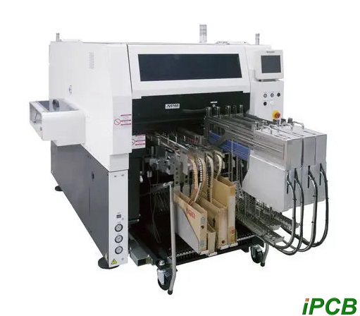
Smt placement machine, also known as “placement machine” or “surface mounting system”, is configured after the dispensing machine or screen printing machine. It is a device that accurately places surface mount components on PCB pads by moving the placement head. It is a device used to achieve high-speed and high-precision placement of components. It is a very critical and complex equipment in the entire SMI production. It is mainly divided into manual and fully automatic.
- Working principle of smt machine – structure and function
There are many types of smt machines at present, but whether it is a fully automatic high-speed smt machine or a manual low-speed smt machine, it is composed of a frame, PCB transmission and bearing mechanism, drive system, positioning and centering system, mounting head, feeder, optical recognition system, sensor and computer control system. Let us briefly introduce its functions:
The frame is the foundation of the machine. All transmission, positioning mechanisms and feeders are firmly fixed on it, so it must have sufficient mechanical strength and rigidity.
PCB transmission and bearing mechanism – the transmission mechanism is an ultra-thin belt transmission system installed on the guide rail. Its function is to send the PCB to the predetermined position and send it to the next process after the smt is mounted.
Drive system – it is the key mechanism of the smt machine and an important indicator for evaluating the accuracy of the smt machine. It includes an XYZ transmission structure and a servo system. Its functions include supporting the movement of the mounting head and supporting the PCB load. - Working principle of smt pick and place equipment – Arch type
Working principle of arch type smt machine: first, the component feeder and substrate are fixed, the smt head moves back and forth between the feeder and the substrate, takes the component out of the feeder, and then adjusts the position and direction of the component before placing it on the substrate.
The advantages of this type of machine are: simple system structure, high precision, suitable for components of various sizes and shapes, even special-shaped components, the feeder has strip, tube, and tray forms. Suitable for small and medium batch production, and multiple machines can also be combined for large-scale production.
- Working principle of smt machine – turret type
The working principle of turret type smt machine is that the component feeder is placed on a single-coordinate moving material cart, the substrate is placed on a workbench moving in an X/Y coordinate system, and the smt head is installed on a turret. When working, the material cart moves the component feeder to the material picking position, and the vacuum suction nozzle on the smt head picks up the component at the material picking position, rotates to the smt position through the turret, and adjusts the position and direction of the component during the rotation process, and then places the component on the substrate.
This model is superior in speed and suitable for mass production, but it can only use components packaged in strips. If it is a dense-footed, large integrated circuit, it cannot be completed with only tray packaging, so it still depends on other models to work together.
I. General process of smt material connection
① Inspection and preparation: First, it is necessary to inspect and prepare the required components, smt machines and related equipment. Confirm whether the smt machine program and setting parameters used are correct to ensure a dust-free and impurity-free working environment.
② Check and place components: According to the BOM list or the requirements of the placement machine program, place the components correctly on the component tray or component reel. This step requires careful checking of the specifications and models of the components to ensure that they are consistent with the program requirements.
③ Set the placement machine parameters: According to the component specifications and the placement machine program requirements, set the appropriate placement machine parameters, such as speed, pressure, and alignment accuracy. Install the correct suction nozzle and the corresponding suction nozzle size.
④ Start the placement machine: Place the PCB (printed circuit board) on the conveyor belt of the placement machine, and start the placement machine to start the automatic or semi-automatic placement process. The placement machine will automatically identify the component position and accurately position it, and paste the component onto the PCB.
⑤ Inspection and welding: After the placement is completed, the placement results need to be checked to ensure that the components are attached accurately and stably. Then carry out the necessary soldering process (such as reflow soldering, wave soldering) or other subsequent processes.
⑥ Visual inspection and functional testing: Finally, perform visual inspection and functional testing to ensure that the placement results meet the requirements.
II.Specific operation steps for smt pick and place equipment
During the specific operation process of material connection, the following steps should also be noted:
① Equipment alarm processing: When the smt machine is not feeding enough materials, the machine will alarm. The operator cancels the alarm according to the machine prompt, and the loader inspects the station where the material needs to be connected.
② Material collection and verification: The loader takes the material from the corresponding station on the material rack according to the station, and checks it with the station number table to check whether the specifications and models are exactly the same. If there is any abnormality, it is necessary to re-collect the material.
③ New and old material tray verification: The loader checks the new material tray with the old material tray to check whether the specifications and models of the two material trays are exactly the same. If there is any abnormality, it is necessary to notify the postponement immediately.
④ Material connection and recording: Cut the materials on the new and old material trays flat, take samples from the new material tray, and connect them. Install the feeder back to the smt machine and copy the specifications and models to the material change record sheet (including bulk materials).
⑤ IPQC material matching: Notify IPQC to check whether the material is correct and whether the site is correct according to the site number table.
III. Precautions for smt material connection
① Component quality control: Select and purchase high-quality components to ensure the correctness and consistency of the components.
② PCB quality control: Ensure the quality and surface finish of the PCB to ensure the stability and quality of the patch adhesion.
③ Temperature and humidity control: Control the ambient temperature and humidity to avoid the components and PCB from being damp or heated, which will affect the patch process and quality.
④ Suction nozzle and alignment accuracy: Select the appropriate suction nozzle size and alignment accuracy to ensure that the components can be accurately grasped and pasted in the correct position.
⑤ Equipment operation specifications: Strictly operate in accordance with the company’s specified smt machine material replacement and material connection process flow to avoid batch product errors caused by improper operation.
⑥ Safe operation: smt equipment is a valuable equipment and needs to be operated safely. At the same time, operators should also pay attention to their own safety.
Surface mounting technology is now the preferred method for automatic production of electronic printed circuit boards. Machines for mounting components in a pick-and-place manner on substrates such as printed circuit boards, or on substrates of system-in-package (SIP) components, are subject to different requirements that are often contradictory, such as mounting speed, mounting accuracy, size, prize, etc.
A person skilled in the art understands the expression “pick-and-place manner” as describing a real mounting operation, in which a mounting head moves to a component feeder area, where it picks up one or more components from one or more component feeders, and then moves to a mounting area, where it places one or more components on a substrate.
A certain type of component, for example a feed of a certain prescribed type of capacitor, resistor, diode or IC, is supplied on a tray or on a rack carrying one type of component, or on a tape, which is most commonly used today, in a roll, in which there are a series of recesses of appropriate depth, holding one component in each recess.
The roll has a variable width between 8 mm and 44 mm. A row of rolls, each roll representing a different type of component, is arranged in a bin, which in turn is arranged in a bin and delivers the components to a pick-and-place machine as a nozzle arm picks up the components from their recesses and places them on a board. Component manufacturers deliver components in standard rolls with recessed tapes with a thin cover tape for closing the recesses. This recess cover tape must be removed by some method before the components can be picked up from their recesses.
Smt pick and place machines that mount components on substrates such as printed circuit boards or system-in-package components in a pick-and-place manner are subject to different, often conflicting requirements, such as mounting speed, mounting precision, size, accuracy, etc. A person skilled in the art will understand the expression “pick-and-place manner” as describing a real mounting operation in which a mounting head in the Smt pick and place machine moves to a component feeder area where it picks up one or more components from one or more component feeders located at predetermined component feeder positions of the pick-and-place machine and then moves to a mounting area where it places one or more components on a substrate. The total machine that arranges all required components for a predetermined number of substrates is called a production Smt pick and place device. An smt job typically includes: smt job data describing all required components, the position of each component on a substrate such as a printed circuit board required to produce an smt product unit, and a planned relative order, wherein the smt job is produced, for example, the third in the order to be produced among 5 planned smt jobs.
In one example, an operator provides a bin including a bin loading unit at a port of an automatic surface mount device warehouse. For example, the bin loading unit in the bin is identified by scanning an identification label or retrieving an associated bin loading unit from an smt information database. A processor in the automatic surface mount device warehouse identifies an available position in the automatic surface mount device warehouse that can accommodate a bin and retrieves a corresponding parameter value from a memory. Then, an actuator deposits the received bin in a retracted position in the automatic surface mount device warehouse and stores the position in the automatic surface mount device warehouse associated with the bin loading unit ID included in the bin in a memory and/or in an smt information database, wherein the bin loading unit ID is, for example, a component tape reel ID or a tray ID.
Although Smt pick and place equipment seems simple, it requires a rigorous attitude and meticulous operation in actual operation. Only by strictly following the process and precautions can the quality of patch and production efficiency be ensured. I hope that the introduction of this article can give you a deeper understanding and knowledge of smt pick and place equipment and precautions.