All design differences between 24 GHz and 77 GHz automotive radar PCB antenna boards fundamentally stem from the distinct physical characteristics of the frequency bands themselves. Frequency determines wavelength, and wavelength directly affects antenna size, signal loss, and radiation efficiency—thereby driving adjustments across every stage of PCB design.
The wavelength at 24 GHz is approximately 12.5 mm. Signal attenuation is relatively moderate, and the requirements for substrate loss control are less stringent, resulting in higher design tolerance. This band is well suited for cost-sensitive, short- to mid-range detection applications within 10–30 meters. Accordingly, 24 GHz PCB antenna board design emphasizes a balance between cost and performance.
In contrast, the wavelength at 77 GHz is only about 3.9 mm, placing it in the millimeter-wave spectrum. Signal attenuation is significantly higher, and performance is extremely sensitive to material loss and layout deviations. Even minor substrate loss or routing inaccuracies may substantially degrade radar performance. Design at 77 GHz therefore prioritizes extreme precision and ultra-low loss, supporting long-range, high-resolution detection beyond 100–200 meters and serving as a core solution for advanced driver assistance systems (ADAS) and higher-level autonomous driving applications.
These inherent frequency-dependent differences lead to clear design distinctions between 24 GHz and 77 GHz automotive radar PCB antenna boards in substrate selection, antenna architecture, routing processes, grounding strategy, and manufacturing precision requirements.
Substrate Selection
For 24 GHz automotive radar PCB antenna boards, tolerance to dielectric loss is relatively higher. Designers can balance cost and performance by selecting medium- to low-loss high-frequency laminates. Common materials include Rogers RO4003C, RO4350B, and Taconic RF-35. These substrates typically feature a dielectric constant (Dk) around 3.5 and a dissipation factor (Df) below 0.004, meeting low-loss transmission requirements at 24 GHz while maintaining reasonable cost.
In cost-sensitive, entry-level parking radar applications, modified FR-4 materials may be used after performance validation, provided that dielectric constant stability is strictly controlled. This approach further reduces manufacturing cost while satisfying basic detection requirements.
For 77 GHz automotive radar PCB antenna boards, substrate loss requirements become far more stringent. Millimeter-wave signals experience substantial attenuation during propagation, and excessive dielectric loss can severely impact detection range and accuracy. Therefore, ultra-low-loss high-frequency laminates are mandatory. Common options include Rogers RO3003, RO4835, and Isola I-Tera MT40.
These materials typically provide dielectric constants ranging from 2.1 to 3.5 and dissipation factors as low as 0.0005–0.003, minimizing transmission loss and ensuring efficient millimeter-wave radiation and reception. Additionally, they must exhibit excellent thermal stability and low moisture absorption to prevent dielectric constant drift under automotive environmental extremes (–40 °C to 150 °C). The significantly higher material cost is one of the key contributors to the overall cost increase of 77 GHz radar PCBs.
Antenna Structure Design
At 24 GHz, antenna elements are relatively large. Based on wavelength calculations (considering dielectric loading), a typical microstrip patch antenna element measures approximately 5 mm. Complex array structures are generally unnecessary; a single element or a small array can satisfy short- to mid-range detection requirements.
Microstrip patch antennas are commonly used due to their simple structure and ease of fabrication. Microstrip line feeding provides layout flexibility, allowing antenna shape and position to be adjusted according to vehicle installation constraints—ideal for parking assistance and blind-spot monitoring modules. Clearance requirements are also relatively relaxed, typically requiring only 3–5 mm of copper-free and component-free area around the radiating region.
At 77 GHz, antenna elements are significantly smaller and highly array-oriented. With a wavelength of approximately 3.9 mm, a microstrip patch element measures roughly 1.5 mm. A single element cannot provide sufficient gain or directivity for long-range, high-precision detection; therefore, large-scale antenna arrays are required.
Dozens or even hundreds of elements are arranged in linear or planar arrays. A precisely designed feed network controls amplitude and phase distribution across each element to achieve high gain, narrow beamwidth, and electronic beam steering capability, thereby improving detection resolution and range accuracy (down to approximately 0.1 m).
The feed network at 77 GHz is considerably more complex. Coplanar waveguide (CPW) or stripline structures are typically used, with strict equal-length and equal-phase routing requirements to maintain phase consistency and prevent beamforming degradation. Clearance requirements are also more stringent: the radiating region must remain fully exposed (no solder mask), and no copper, routing, or components are allowed within 5–8 mm to avoid coupling loss. This significantly increases layout complexity and integration challenges.
Routing and Manufacturing Process
Routing requirements at 24 GHz are comparatively relaxed. The primary objective is maintaining 50 Ω impedance matching. Microstrip line width, depending on substrate thickness, is typically around 0.6 mm (1 oz copper, 1.6 mm board thickness), with a tolerance of ±0.05 mm sufficient for performance requirements.
Right-angle traces should be avoided in favor of 45° bends or curved routing to minimize reflection. Feed paths should be as short as possible and must not cross ground plane splits. Standard etching processes are generally sufficient. Through-holes of approximately 0.3 mm diameter are acceptable. ENIG (Electroless Nickel Immersion Gold) surface finish with gold thickness of 0.05–0.1 µm provides solderability and low RF loss. Overall, manufacturing complexity is moderate and suitable for mass production.
In contrast, 77 GHz PCB antenna boards demand extreme precision. At such high frequencies, parasitic effects strongly influence performance. Coplanar waveguide trace widths may be as narrow as 0.15 mm (½ oz copper), with ground spacing around 0.2 mm. Line width tolerance must be controlled within ±0.005 mm, typically requiring laser direct imaging (LDI) or precision etching processes.
Blind vias (approximately 0.2 mm diameter) are preferred, combined with back-drilling to reduce via stub length below 0.2 mm, minimizing parasitic inductance and capacitance and preventing signal reflection. Suitable high-frequency surface finishes such as ENIG or immersion silver are required; HASL is not acceptable due to surface unevenness and performance degradation at millimeter-wave frequencies.
To meet automotive reliability standards, 77 GHz PCBs typically use multilayer stack-ups (4–8 layers or more). Dense ground via stitching (≤1 mm spacing) ensures ground impedance ≤0.03 Ω and reduces ground noise and EMI. Layer-to-layer registration must be tightly controlled, with misalignment limited to ≤0.075 mm to avoid degrading antenna array performance.
Grounding and Shielding Design
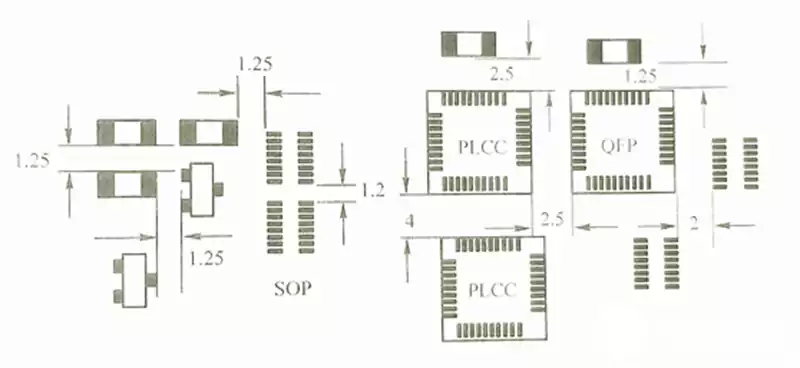
At 24 GHz, grounding design is relatively straightforward. A continuous ground plane provides a low-impedance return path. Ground vias spaced approximately 1.25 mm apart (about λ/10) can form via fences to enhance shielding. RF ground and digital ground are typically connected at a single point near the power entry to minimize common-mode interference. Shielding enclosures can be mechanically reserved with a height above 3 mm to prevent self-resonance. Complex shielding structures are generally unnecessary for short-range applications.
At 77 GHz, grounding and shielding requirements are significantly stricter. Millimeter-wave signals are highly susceptible to interference and may also radiate into other sensitive automotive circuits. A continuous, unbroken ground plane is mandatory, reinforced by dense via stitching (≤1 mm spacing) to maintain equipotential grounding and ultra-low return path impedance.
The RF section must be enclosed with a metal shielding cover (approximately 0.3 mm thick), soldered to the ground layer, achieving shielding effectiveness of at least 60 dB to suppress external interference and internal leakage.
Furthermore, strict partitioning between RF, digital, and power domains is required. The RF section should maintain a minimum distance of 30 mm from potential interference sources such as automotive ECUs. TX and RX traces should be spaced at least three times the board thickness to achieve channel isolation typically exceeding 30 dB, preventing crosstalk and ensuring detection accuracy.
In summary, the differences between 24 GHz and 77 GHz automotive radar PCB antenna boards fundamentally arise from frequency-driven electromagnetic characteristics. As frequency increases and wavelength decreases, requirements for dimensional precision, material loss control, phase consistency, and grounding integrity become progressively stricter. At the same time, manufacturing complexity and cost increase accordingly.
Understanding this frequency-dependent design logic is essential for making appropriate engineering trade-offs among performance, manufacturability, and cost in automotive radar PCB development.