In drone pcb board design, the printed circuit board directly impacts signal stability, flight safety and flight endurance. Striking the right balance between performance, cost, weight and reliability is key to selecting the appropriate number of PCB layers.
The reason why 4-layer and 6-layer boards have become the mainstream solutions for consumer-grade and industrial-grade applications, respectively, is that they precisely meet the practical requirements of each sector in terms of functional compatibility, structural design and manufacturing processes.
For most consumer-grade drones, a 4-layer PCB represents the optimal choice for balancing performance and cost. Its typical stack-up structure is ‘signal layer – power layer – ground layer – signal layer’. This design precisely meets the functional requirements of consumer-grade drones and is the key reason why 4-layer PCBs have become the mainstream choice in this sector.
The core functions of consumer-grade drones primarily revolve around basic flight control, short-range video transmission, remote control signal reception and battery management. Component density is moderate, requiring no overly complex routing, but placing high demands on signal stability and lightweight design.
By designating the middle two layers of a 4-layer board as independent power and ground planes, a complete electromagnetic shielding structure can be established, effectively isolating interference between digital and analogue signals. This is particularly crucial because flight control signals are high-precision analogue signals, whilst video transmission and remote control signals are high-frequency digital signals; should these interfere with one another, it could lead to loss of flight control or video transmission stuttering. The design of a dedicated ground plane also helps to reduce ground bounce noise and minimise signal reflection losses, ensuring the precise transmission of flight control commands; this constitutes the core advantage of the 4-layer board in terms of signal integrity.
Lightweight design is a key competitive advantage for consumer-grade drones. The thickness of a 4-layer board is typically kept between 1.2 and 1.6 mm; its weight is significantly lower than that of 6-layer or multi-layer boards, meaning it does not significantly increase the load on the airframe, thereby helping to extend flight time. At the same time, the manufacturing costs of 4-layer boards are relatively manageable; they do not require complex interlayer lamination or blind/buried via processes, making them suitable for mass production and capable of meeting the cost-effectiveness requirements of consumer-grade products.
Taking common consumer-grade aerial photography drones as an example, their flight control boards mostly adopt a 4-layer PCB design. By optimising the stack-up layout, stable isolation of 2.4GHz and 5.8GHz dual-frequency signals can be achieved, ensuring both remote control range and video transmission quality whilst effectively controlling costs. This is precisely the core rationale behind the widespread application of 4-layer circuit boards in the consumer market.
Furthermore, the structural strength of 4-layer boards is sufficient to withstand the vibrations encountered during the flight of consumer-grade drones. As consumer-grade products typically operate at low altitudes, the amplitude of vibrations is relatively mild. 4-layer PCBs utilising high-Tg FR4 substrate ensure sufficient mechanical strength whilst maintaining a lightweight design, effectively preventing issues such as circuit breaks or solder joint detachment caused by vibrations. In terms of heat dissipation, the copper-clad design of the power and ground layers in 4-layer boards enables rapid dissipation of heat generated by the chips during operation. This prevents performance degradation caused by overheating and ensures the continuous, stable operation of the drone.
As the applications of drone pcb boards extend into fields such as industrial inspection, agricultural plant protection and border patrol, the performance requirements for circuit boards in industrial-grade drones have risen significantly—higher component density, more complex signal transmission and greater environmental resilience make 6-layer PCBs the obvious choice. Their layered structure typically follows the sequence ‘signal layer – ground layer – signal layer – power layer – ground layer – signal layer’, with the two additional signal layers delivering a qualitative improvement in the circuit board’s performance.
Industrial grade drones often integrate multiple functional modules such as high-definition video transmission, infrared temperature measurement, satellite navigation and multi-sensor fusion, resulting in a substantial increase in component density and significantly greater routing complexity. By adding signal layers, 6-layer boards enable more precise routing planning, allowing digital, analogue and high-frequency signals to be arranged on separate layers, thereby preventing interference between different signal types at source.
For example, the video transmission signals of industrial inspection drones are predominantly 5.8GHz high-frequency signals. If these share the same routing layer with the flight controller’s analogue signals, it would result in severe signal attenuation, affecting transmission range and clarity. In contrast, a 6-layer board can isolate the high-frequency video transmission signal onto a dedicated layer. By utilising the shielding effect of adjacent ground layers, signal loss is minimised, ensuring the stability of beyond-line-of-sight communication. This represents a core advantage of 6-layer circuit boards in complex signal processing.
The operating environment of industrial-grade drones is particularly challenging, with factors such as high and low temperatures, intense vibration, salt spray and dust all posing significant threats to circuit board reliability. 6 layer boards employ a more complex interlayer lamination process, resulting in a more robust structure. Combined with high-Tg FR4 or even ceramic substrates, they can enhance resistance to high and low temperatures, maintaining stable operation across a wide temperature range of -40°C to 85°C and preventing issues such as delamination between layers or copper foil oxidation caused by temperature cycling.
Furthermore, 6 layer boards offer superior heat dissipation. Through the use of multi-layer copper cladding and heat-dissipating vias, they can rapidly dissipate the heat generated by high-power chips (such as ESC chips and power amplifiers). For instance, after adopting a 6-layer PCB design for the ESC board of a certain agricultural crop protection drone, the MOSFET junction temperature was reduced by 39.6%, effectively preventing flight interruptions caused by thermal shutdown.
For industrial-grade drones, reliability is far more important than cost. The 6-layer board design facilitates the implementation of redundancy and backup systems. By separating critical signals from standard signals through layered routing, even if a fault occurs on a single layer, it will not affect the normal operation of core functions, significantly enhancing the system’s fault tolerance.
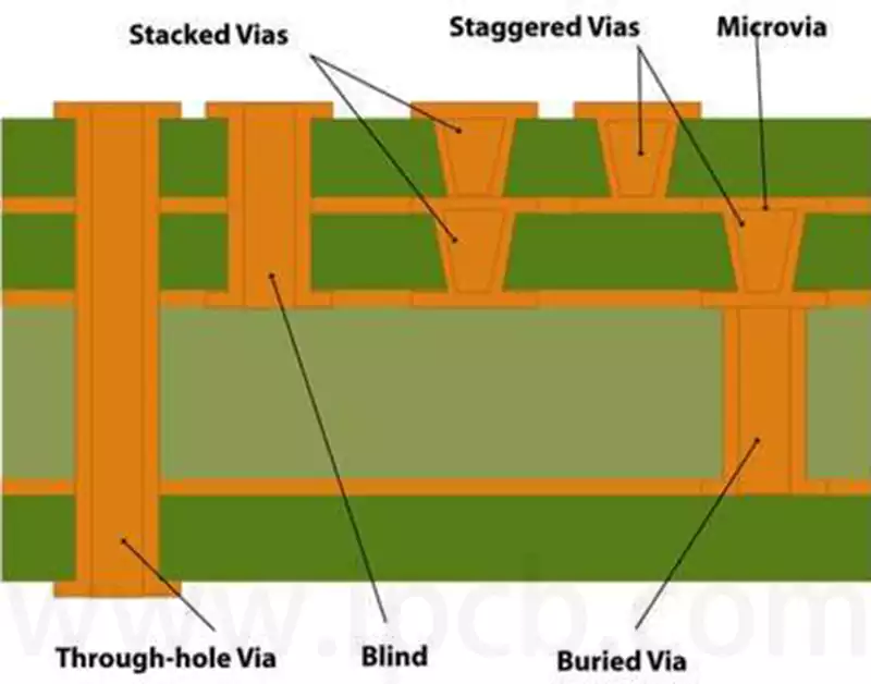
For example, the core flight control signals in industrial-grade inspection drones employ a dual-layer routing design, with signals arranged on separate signal layers. This ensures precise flight attitude control even under extreme conditions, thereby guaranteeing flight safety. Furthermore, 6-layer boards allow for the incorporation of blind and buried via technology, increasing space utilisation by over 30%. This reduces the size of the circuit board whilst enhancing component integration, better aligning with the trend towards miniaturisation and multi-functionality in industrial-grade drones.
Why are single-layer, double-layer or high-layer boards (8 layers or more) not used for drone pcb boards?
The limitations of single-layer and double-layer boards are quite evident. Single-layer boards allow routing on only one side of the substrate; with limited space, it is difficult to integrate the multi-module components required by drones. Furthermore, the absence of dedicated power and ground planes leads to severe signal interference, making it impossible to guarantee the stability of flight control and video transmission signals.
As such, they are only suitable for simple toy drones and cannot meet the demands of consumer-grade or industrial-grade applications. Although double-layer boards offer improved routing space, they still lack sufficient shielding layers, resulting in poor signal isolation. Their heat dissipation performance is also limited, making them prone to performance degradation due to overheating during prolonged drone operation; consequently, they are equally unlikely to become a mainstream choice.
Whilst high-layer boards with eight or more layers offer advantages in signal shielding, heat dissipation and routing space, they are not entirely suitable for drone applications. High-layer PCBs are relatively heavy, significantly increasing the load on the airframe and reducing flight time; this is a clear drawback for drones that rely on flight endurance.
Furthermore, their high manufacturing costs, complex processes and long production cycles make it difficult to achieve a good balance between cost and performance, whether for the mass production of consumer-grade products or the customisation requirements of industrial-grade products. Furthermore, given the limited dimensions of drone pcb boards, the greater thickness of high-layer count boards hinders miniaturisation efforts.
Moreover, the redundant layers may actually increase signal reflection, thereby compromising signal stability—field tests indicate that a well-designed 6-layer layout may offer more stable signal performance than a poorly executed 8-layer design, which confirms the industry consensus that ‘more layers are not necessarily better’.
Regarding material selection, to meet the requirements for lightweight construction and environmental resilience in drones, designs typically utilise high-Tg FR4 substrate. This material features a high glass transition temperature, good mechanical strength and low weight, thereby reducing the load on the airframe whilst ensuring PCB stability.
For the high-frequency signal requirements of industrial-grade drones, high-frequency laminates such as RO4350B can be selected to minimise high-frequency signal attenuation and enhance communication stability. The selection of copper foil thickness also requires precise matching: consumer-grade drones may use 1 oz copper foil to balance conductivity and weight; high-power modules in industrial-grade drones may use 2 oz copper foil to reduce line losses and enhance heat dissipation.
In terms of process control, 4-layer and 6-layer drone pcb boards place high demands on interlayer alignment accuracy, via quality and solder mask processes. Interlayer alignment accuracy must be controlled within ±0.05 mm to prevent signal short circuits or open circuits caused by interlayer misalignment; laser drilling technology is employed for vias to ensure uniform hole diameters and smooth walls, thereby enhancing the reliability of interlayer interconnections; the solder mask process utilises thin photosensitive ink to avoid excessive coating thickness affecting signal transmission, whilst simultaneously improving the PCB’s corrosion resistance to meet the operational requirements of industrial-grade drones in complex environments.
To address the vibration tolerance requirements of UAVs, laser reflow soldering technology is introduced during the soldering process to achieve precise local temperature control. This effectively resolves issues arising from mismatched thermal expansion coefficients between components and the PCB, thereby enhancing the fatigue resistance of solder joints.
In terms of quality inspection, a comprehensive reliability testing system covering the entire production process has been established, including high and low-temperature cycling tests, vibration tests, salt spray tests, and signal integrity tests. High and low-temperature cycling tests are used to verify the PCB’s ability to operate fault-free within the range of -40°C to 85°C; vibration tests simulate high-frequency vibrations encountered during flight to assess the stability of solder joints and circuits; salt spray tests evaluate corrosion resistance in coastal and field environments; whilst signal integrity tests ensure stable high-frequency signal transmission, preventing signal attenuation and interference. Through rigorous testing procedures, we ensure that every 4-layer or 6-layer drone pcb board meets flight requirements, thereby enhancing product reliability and service life.
From consumer-grade to industrial-grade applications, the selection of circuit board layer counts consistently adheres to the principles of scenario-driven design, performance prioritisation and cost control. Through systematic optimisation of the laminate structure, material processes and testing systems, 4-layer and 6-layer PCBs continue to support the safe and stable operation of drone pcb boards across a wide range of scenarios.