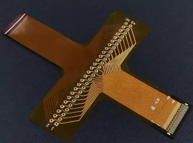
Flexible printed circuit boards (FPCs), also known as flexible PCBs, are an important category of printed circuit boards. However, they differ fundamentally from conventional rigid PCBs in terms of materials, performance, and application scenarios. Most FPCs are manufactured using polyimide (PI) flexible substrates, which offer exceptional flexibility and can withstand repeated bending, folding, twisting, and stretching.
Originally developed primarily for connecting miniature electronic components and accommodating dynamic bending applications, FPCs have become indispensable in today’s consumer electronics industry. As smartphones continue to evolve toward foldable and ultra-portable designs, flexible circuits have emerged as essential components that enable the next generation of bendable electronic devices.
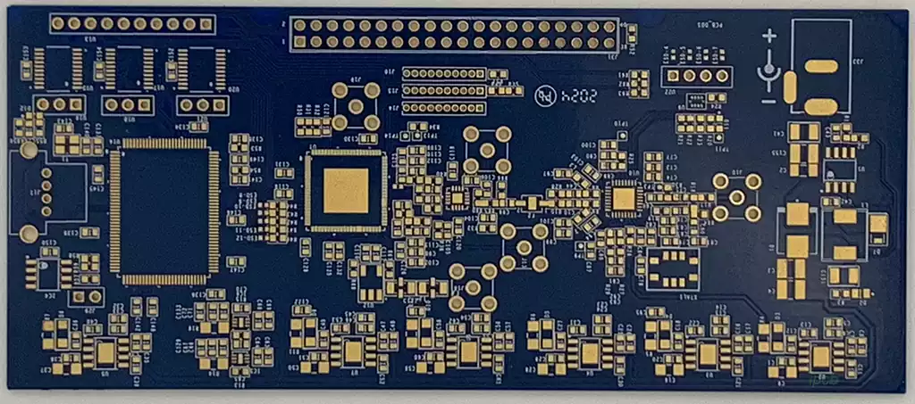
In contrast, conventional rigid PCBs are primarily manufactured using FR-4 substrates. Their rigid structure provides excellent mechanical strength but cannot be bent or deformed, making them the ideal platform for mounting and supporting electronic components. Rigid PCBs are widely used in applications that require structural stability rather than flexibility, such as computer motherboards, conventional smartphone mainboards, and numerous other electronic assemblies.
The structural differences between flexible and rigid circuit boards become even more apparent during product design. Conventional rigid PCBs are limited to planar circuit layouts. Although three-dimensional electrical interconnections can be achieved through additional assembly processes such as connectors, cables, or encapsulation, these solutions increase manufacturing complexity and impose significant design limitations.
FPCs, by contrast, naturally support three-dimensional circuit routing thanks to their inherent flexibility, allowing designers to make full use of the available internal space within electronic devices. Moreover, a single flexible circuit can integrate multiple rigid sections into one continuous electrical assembly, eliminating the need for many conventional connectors, terminals, and wiring harnesses. This not only reduces signal interference at connection points but also improves signal integrity and enhances the overall reliability of the finished product.
When it comes to space optimization, rigid PCBs typically require expansion boards, connectors, or adapter cards to increase routing capacity, resulting in larger and more complicated assemblies. Flexible circuits achieve similar functionality with much simpler interconnection designs while allowing routing paths to follow virtually any angle or contour required by the product enclosure. Multiple rigid sections can also be interconnected by flexible circuits to form parallel or folded circuit architectures, making FPCs particularly well suited for compact, lightweight, and irregularly shaped electronic products.
Rigid-flex PCBs differ from standard flexible circuit boards in both structure and functionality. A rigid-flex PCB is manufactured by laminating FR-4 rigid materials and PI flexible materials into a single integrated board through a high-pressure lamination process. This hybrid construction combines the mechanical strength of rigid PCBs with the flexibility of FPCs, overcoming the limitations of conventional planar circuit layouts while enabling complex three-dimensional circuit structures. Rigid-flex technology can replace complicated assemblies consisting of multiple connectors and cables, helping electronic products become smaller, lighter, and more reliable while improving overall electrical and mechanical performance.
The primary distinction between the two lies in their flexibility. A pure FPC can bend freely across the entire board, whereas only the designated flexible sections of a rigid-flex PCB are capable of bending, while the rigid sections remain mechanically stable. Manufacturing complexity is another major difference. Rigid-flex PCBs require considerably more sophisticated fabrication processes and tighter process control, resulting in significantly higher production costs than standard flexible circuits. Their application scenarios also differ. Because rigid-flex boards combine rigid support with flexible interconnections, they are specifically designed for products that require both structural reinforcement and localized bending, allowing engineers to simplify internal layouts, reduce product size, and improve overall system reliability.
The performance of an FPC largely depends on its constituent materials, with flexible copper clad laminate (FCCL) serving as the foundation of the circuit. Common substrate materials include polyimide (PI), polyester (PET), polyethylene naphthalate (PEN), and liquid crystal polymer (LCP). As the primary structural material of an FPC, FCCL provides electrical insulation, supports conductive circuitry, and maintains the mechanical integrity of the board, making it one of the most critical factors affecting the overall performance of the finished product.
The coverlay consists of a polymer film laminated with a specially formulated adhesive. Its primary function is to encapsulate and protect the copper circuitry from oxidation, mechanical wear, short circuits, and environmental contamination, thereby ensuring long-term electrical reliability and circuit stability.
Bonding films are available in both adhesive-backed and adhesive-free configurations and are offered in a variety of material systems and thicknesses. They are primarily used to bond together multiple flexible circuit layers while simultaneously providing electrical insulation, making them essential materials in the manufacture of multilayer FPCs.
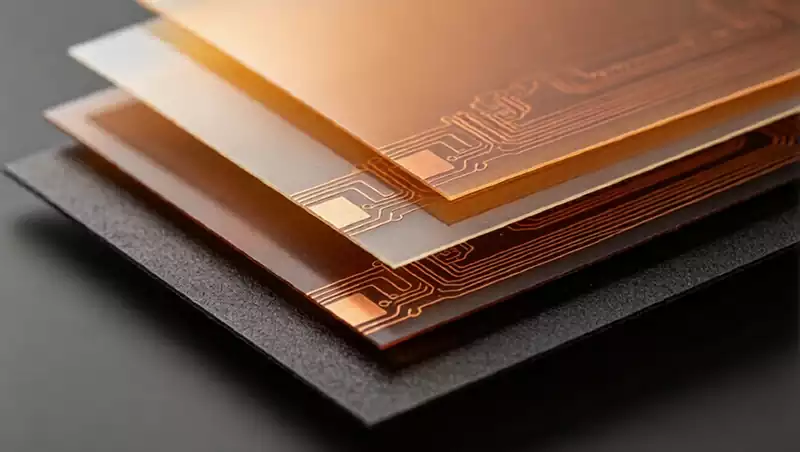
A standard single-layer FPC generally consists of a base material and a coverlay. The base material itself is a composite structure formed by laminating an insulating film, adhesive, and copper foil. Today, polyimide is the industry’s preferred substrate because of its excellent thermal resistance, superior flexural endurance, and outstanding long-term reliability. Its primary disadvantage is cost, as PI substrates are typically around twice as expensive as PET materials. Although PET substrates offer lower manufacturing costs, their relatively poor heat resistance and limited bending life have led to their gradual replacement in most high-performance applications.
PI base materials, PI coverlays, and PI stiffeners each serve distinct purposes within an FPC structure. PI base materials, available in both adhesive-based and adhesive-free versions, form the structural foundation on which all conductive traces are fabricated. PI coverlays provide electrical insulation and protect copper circuits from external environmental influences. PI stiffeners are commonly added beneath insertion areas such as gold fingers and connector interfaces to increase local thickness and mechanical rigidity. This reinforcement improves insertion durability, enhances connection stability, and prevents deformation or poor electrical contact caused by excessive flexibility.
These three materials also differ significantly in thickness specifications. PI base materials are commonly available in thicknesses of 1/2 mil and 1 mil, while premium adhesive-free PI materials manufactured by leading suppliers can reach thicknesses of approximately 4 to 5 mil. PI coverlays are generally standardized in 1/2 mil and 1 mil thicknesses. PI stiffeners, however, are available in a much wider range of thicknesses to meet different design requirements, with common options including 0.075 mm, 0.10 mm, 0.125 mm, and 0.25 mm.
Their appearance also varies. PI base materials are supplied only in their natural color and do not offer color options. PI coverlays are commonly available in yellow, white, and black to satisfy different product requirements. PI stiffeners gradually become darker as thickness increases, with 0.075 mm stiffeners typically appearing light brown and 0.25 mm versions approaching black.
Compared with conventional rigid PCBs, flexible printed circuit boards offer a range of performance advantages that cannot easily be replicated by rigid technologies. Their ability to bend, fold, twist, and conform to three-dimensional product geometries enables highly integrated circuit designs while maximizing the utilization of available internal space. This significantly reduces both the size and weight of electronic devices, making FPCs an ideal solution for the continuing trend toward higher circuit density, product miniaturization, and improved reliability across modern electronic applications.