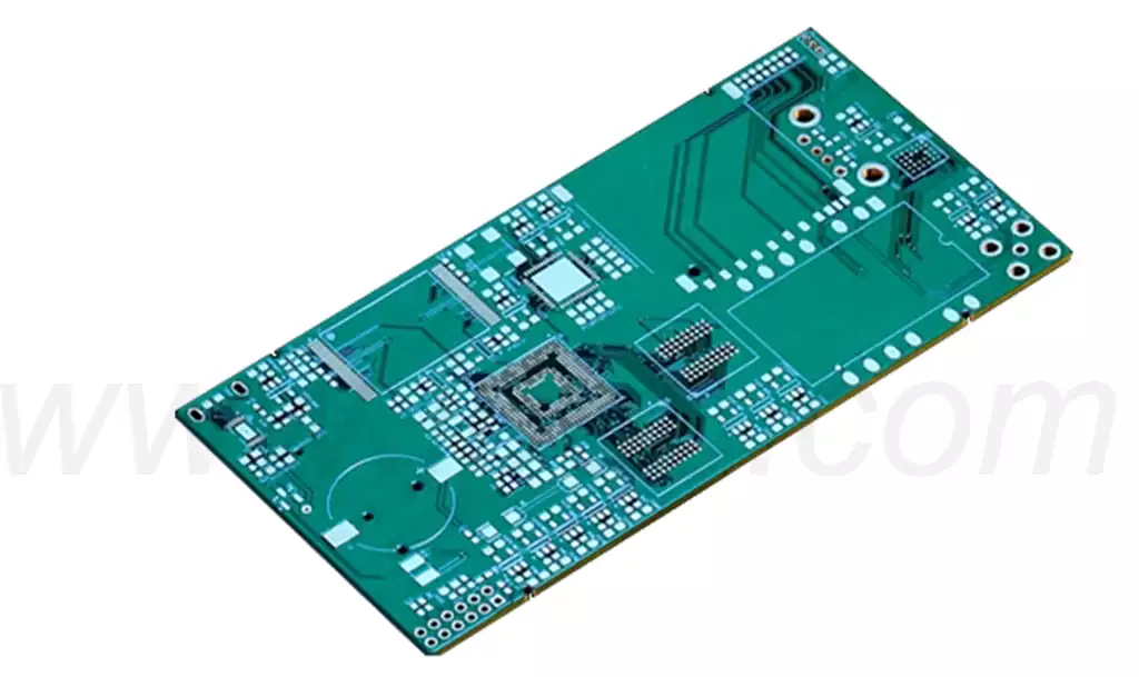
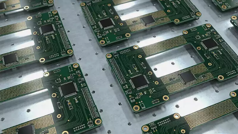
A PCBA test fixture is a custom-built testing tool specifically designed for assembled printed circuit board assemblies (PCBAs) in the electronics manufacturing industry. As a non-standard automated testing solution, it is used to perform standardized electrical and functional inspections on finished PCBAs during mass production quality control. To ensure accurate fixture compatibility and reliable test performance, PCB manufacturers typically provide fixture suppliers with complete Gerber files and physical PCBA samples. These serve as the foundation for fixture design, probe layout, mechanical structure, and functional debugging.
Core Principles and Applications of PCBA Test Fixtures
1.Custom-Designed to Match Specific PCBA Testing Requirements
Unlike standardized testing equipment, every PCBA test fixture is custom-designed according to the dimensions, test point layout, and electrical characteristics of the target circuit board. Engineers carefully analyze the board architecture, signal routing, and critical test nodes before designing the probe arrangement, fixture structure, and testing program. This customized approach ensures complete coverage of all critical test points, enabling accurate fault detection and functional verification while providing the first line of quality assurance for every production PCBA.
2.Detecting Defects Early to Reduce Costs and Improve Manufacturing Efficiency
During high-volume PCB assembly, defects such as poor solder joints, faulty electronic components, and assembly errors can occur repeatedly if left undetected. A PCBA test fixture identifies both visible and hidden defects at an early production stage, including component failures, soldering defects, incorrect component placement, and electrical continuity issues.
By detecting defective boards before they proceed to subsequent processes such as final assembly, burn-in testing, or system integration, manufacturers can minimize material waste, reduce rework costs, prevent production delays, and significantly improve manufacturing efficiency. In addition, the detailed fault data generated during testing helps engineers identify root causes and continuously optimize SMT assembly, soldering, and other manufacturing processes to improve production yield.
3.Replacing Manual Inspection to Increase Production Efficiency
Traditional manual testing relies heavily on operator experience, making it relatively slow and unsuitable for large-scale production. It is also vulnerable to human error, inconsistent judgments, and missed defects.
A PCBA test fixture automates the entire inspection process through standardized testing programs, enabling fast, repeatable, and highly accurate testing on production lines. By eliminating human variability, it ensures consistent testing standards for every PCBA while significantly increasing inspection speed and supporting high-volume manufacturing.
4.Standardizing Quality Inspection to Ensure Product Consistency
Maintaining consistent product quality across mass production is one of the biggest challenges in electronics manufacturing. A PCBA test fixture performs identical electrical tests, functional verification, and parameter evaluation on every board of the same model using standardized testing procedures. This guarantees that every shipped PCBA meets the original design specifications and quality requirements, minimizing product variation while improving product reliability, brand reputation, and customer confidence.
5.Supporting Multiple Products with Excellent Flexibility
Modern electronics manufacturing requires testing equipment capable of adapting to frequent product updates and multiple product variants. PCBA test fixtures offer excellent flexibility and compatibility. Without major modifications to the fixture platform, manufacturers can accommodate different PCBAs simply by replacing fixture plates, updating test programs, or adjusting probe configurations.
This flexibility makes PCBA test fixtures well suited for high-mix, low-volume manufacturing as well as rapid product iteration, making them an indispensable tool in modern electronics quality control.
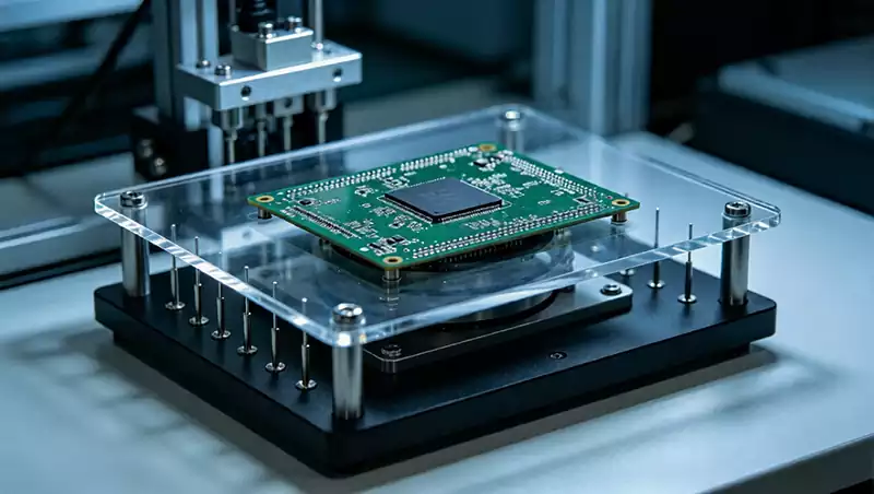
PCBA Test Fixture Manufacturing Process
1.Material Preparation
Based on the specifications of the target PCBA and the testing requirements, all necessary materials are prepared before manufacturing begins. These include electronic components, auxiliary control circuits, testing modules, acrylic fixture plates, mounting screws, dedicated wiring, industrial adhesives, power tools, and other structural materials. Every component is prepared according to the custom fixture design to ensure smooth assembly.
2.Mechanical Structure Design and Verification
The overall fixture structure is finalized according to the dimensions of the PCBA sample, test point distribution, and intended application. Engineers determine the fixture mounting method, probe arrangement, support structure, and other key mechanical parameters before verifying the design to eliminate potential issues such as structural interference, probe misalignment, or insufficient fixture stability.
3.Standardized Wiring Assembly
The wiring process directly affects both testing accuracy and operational safety and must strictly follow standardized manufacturing requirements.
The insulation stripping length of each wire should not exceed 2 mm. Wire ends and probe solder pads should be pre-tinned before soldering to ensure reliable electrical connections.
All solder joints must be secure, with no loose wiring, cold solder joints, or detached connections.
High-voltage and low-voltage wiring should be routed separately and neatly secured with cable ties to minimize electrical interference.
Current and voltage measurement ports should use multimeter-style probe connectors instead of conventional banana plugs to improve operator safety.
Signal wiring for high-frequency test equipment should use shielded cables with proper grounding to eliminate electromagnetic interference.
Test fixtures equipped with internal power transformers must have their metal enclosures properly grounded.
Every test fixture must include a correctly rated fuse. Conductors or metal wires must never be used as substitutes. The original 13 A plug fuse should be replaced with an appropriately rated fuse selected according to the operating current of the tested product, typically 8 to 10 times the normal operating current to ensure adequate load protection.
4.Test Point Optimization and Verification
The selection of test points follows three fundamental principles: complete coverage, measurement accuracy, and optimized efficiency. Every critical circuit, signal path, and functional node must be included without creating testing blind spots. At the same time, probe placement should be optimized to eliminate unnecessary test points, simplify fixture construction, and reduce manufacturing costs while maintaining comprehensive inspection capability.
By combining customization with automated testing, PCBA test fixtures effectively overcome the limitations of manual inspection. They provide fast, accurate, and repeatable verification of circuit board quality and electrical performance, making them an essential tool for ensuring consistent PCBA quality in modern electronic manufacturing.