An Aluminum Base PCB is a specialized metal core printed circuit board (MCPCB) that uses an aluminum alloy substrate as its core material instead of conventional FR-4 glass fiber laminate. It is specifically engineered to provide superior heat dissipation and enhanced mechanical support for high-power electronic devices. Thanks to its excellent thermal management capability and structural rigidity, aluminum base PCBs are widely used in power electronics, LED lighting, automotive electronics, power supplies, and other high-power applications.
Three-Layer Structure of an Aluminum Base PCB
Circuit Layer
The circuit layer is fabricated from high-purity electrolytic copper foil, providing excellent electrical conductivity and high current-carrying capacity. It is designed to accommodate the high-current requirements of power electronic circuits while ensuring stable and reliable electrical performance.
Thermally Conductive Dielectric Layer (Core Functional Layer)
The dielectric layer is the defining feature that distinguishes an aluminum base PCB from a conventional FR-4 PCB. It is typically manufactured from a ceramic-filled, thermally conductive modified epoxy resin, offering both high dielectric strength and excellent thermal conductivity. This unique structure efficiently transfers heat away from electronic components while maintaining complete electrical insulation, effectively solving the challenge of achieving high thermal conductivity without electrical conduction.
Metal Base Layer
The metal base is typically manufactured from 1060 or 6061 aluminum alloy, both of which offer excellent thermal conductivity. This layer rapidly transfers heat generated by electronic components away from the circuit while providing outstanding mechanical rigidity to prevent board deformation during assembly and operation.
Key Advantages of Aluminum Base PCBs
1.Superior Thermal Performance Compared with Conventional FR-4 PCBs
Standard FR-4 laminates typically have a thermal conductivity of only 0.3–0.5 W/(m·K), making them unsuitable for efficient heat dissipation in high-power applications. In contrast, aluminum base PCBs provide an overall thermal conductivity ranging from 1 to 20 W/(m·K), depending on the dielectric material and board construction. The aluminum substrate conducts heat hundreds of times more efficiently than conventional FR-4, allowing heat to be transferred away from power devices much more rapidly.
Lower junction temperatures help reduce LED lumen depreciation, minimize thermal aging of semiconductor devices, improve operating stability, and significantly extend the service life of electronic products.
2.Excellent Mechanical Stability for Diverse Applications
Aluminum base PCBs offer outstanding mechanical strength, high rigidity, and excellent resistance to deformation, vibration, and mechanical impact. In many power electronic applications, they provide a cost-effective alternative to fragile ceramic substrates while maintaining excellent thermal performance.
With an aluminum density of approximately 2.7 g/cm³, aluminum substrates also provide an ideal balance between strength and weight. Their lightweight characteristics make them particularly suitable for automotive electronics, portable electronic devices, LED lighting modules, and compact power modules requiring high reliability and reduced overall system weight.
3.Simplified Thermal Design and Lower Overall System Cost
Because of their excellent inherent heat dissipation capability, aluminum base PCBs can often reduce or eliminate the need for oversized external heat sinks. This enables designers to simplify product structures, reduce the number of mechanical components, and lower tooling, assembly, and material costs.
In addition, aluminum base PCBs are fully compatible with standard SMT assembly processes, comply with RoHS environmental requirements, and provide a certain degree of electromagnetic shielding due to the metal substrate, helping simplify EMI management in many applications.
4.Better Thermal Compatibility and Higher Reliability
The coefficient of thermal expansion (CTE) of aluminum base PCBs is well matched with that of many mainstream semiconductor packages and electronic components. During repeated thermal cycling, this compatibility helps reduce thermal stress on solder joints, minimizing the risk of solder cracking, solder fatigue, and cold solder joints.
As a result, aluminum base PCBs significantly improve solder joint reliability, enhance long-term operational stability, and reduce the likelihood of field failures in high-power electronic equipment.
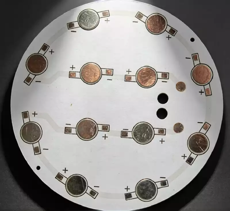
Aluminum Base PCB Design Guidelines and Key Considerations
The performance of an aluminum base PCB is determined not only by the quality of its materials but also by the effectiveness of its structural design. During the design stage, every layer of the board must be carefully specified to achieve the desired balance between electrical performance, thermal management, mechanical strength, and long-term reliability.
The copper circuit layer generally uses heavy copper foil ranging from 1 oz to 4 oz. As the carrier of electrical traces and solder pads for power devices, thicker copper not only increases current-carrying capacity but also improves lateral heat spreading, making it particularly suitable for high-power applications.
The thermally conductive dielectric layer is the most critical part of the entire structure. It is typically manufactured from ceramic-filled polymer materials that combine high thermal conductivity with excellent electrical insulation. When selecting this layer, designers should carefully evaluate its thermal conductivity, dielectric strength, and insulation thickness. In most applications, the dielectric breakdown voltage should be no less than 2 kV AC/DC, while all material specifications should comply with applicable electrical safety standards to eliminate the risk of dielectric breakdown or electrical leakage.
The aluminum base layer, which is commonly manufactured from 6061 or 6063 aluminum alloy, serves as the primary heat transfer path for the entire PCB. During operation, heat generated by electronic components is conducted through the dielectric layer into the aluminum substrate and then transferred directly to the external heat sink, allowing heat to dissipate rapidly while providing sufficient rigidity to prevent mechanical deformation.
Single-Sided PCB Design Principles
Because of the characteristics of thermally conductive dielectric materials and current manufacturing processes, aluminum base PCBs are almost always designed as single-sided boards. The dielectric layer cannot withstand the repeated high-temperature lamination cycles required for multilayer PCB fabrication. Although double-sided and multilayer aluminum base PCBs are technically feasible, they involve significantly higher manufacturing complexity and production costs and are therefore reserved for only a few specialized applications.
For this reason, all electronic components and copper traces should be placed exclusively on the top copper layer. The aluminum substrate itself should never be used for circuit routing or component mounting. Instead, it functions solely as a thermal dissipation layer and structural support, except in a limited number of special embedded-component designs.
Thermal Layout and Heat Flow Optimization
Thermal management is the primary objective of aluminum base PCB design, and careful component placement plays a critical role in reducing overall thermal resistance.
Heat-generating components such as power MOSFETs, high-power LEDs, bridge rectifiers, and other power semiconductor devices should be positioned as close as possible to the center of the board or directly above the heat sink mounting area. This arrangement shortens the heat conduction path and enables heat to flow more efficiently into the aluminum substrate.
The thermal path should also be optimized wherever possible. Large copper areas around high-power components help distribute heat more evenly across the circuit layer, while complete contact between the copper pads and the dielectric layer minimizes thermal resistance. Openings or slots beneath power device pads should be avoided, except for necessary solder mask openings, as they interrupt the heat transfer path. During final assembly, thermal interface materials such as thermal pads or thermal grease should be applied between the PCB and the heat sink to eliminate air gaps and further improve heat transfer efficiency.
Unlike conventional multilayer PCBs, aluminum base PCBs generally do not employ thermal vias. Since the aluminum substrate itself already provides the primary thermal conduction path and is electrically isolated by the dielectric layer, additional through-hole vias contribute little to thermal performance while increasing manufacturing complexity. As a result, standard aluminum base PCB designs typically avoid via structures unless they are required for special mechanical or electrical purposes.