Rigid flex circuit boards can operate successfully after being folded into an enclosure yet fail when the same flexible section moves repeatedly during normal use. A prototype may pass electrical inspection and initial functional testing, but weeks or months of opening, rotating or sliding motion can produce intermittent connections.
The reason is that the ability to complete one installation bend does not prove dynamic flex life. Repeated motion subjects copper conductors, dielectric materials and rigid-to-flex transition zones to continuous mechanical fatigue. Reliability depends on where the circuit bends, how its layers are arranged and whether the final product controls that movement.
One Board Can Face Two Types of Bending
A flex-to-install circuit is bent during product assembly and then remains in a nearly fixed position. It may connect two rigid sections located at different angles or fold into a restricted enclosure. The circuit still requires a controlled bend, but it is not expected to complete thousands of operating cycles.
A dynamic flex PCB moves throughout the product’s service life. Typical motion may occur in a display hinge, rotating sensor, scanning mechanism or adjustable control unit. Each cycle stretches one side of the copper and compresses the other.
These two conditions should not be treated as equivalent. Rigid flex circuit boards intended for dynamic movement usually need a more flexible stackup, a stable bending path and stricter control of conductor geometry than circuits folded only during installation.
The intended operating condition should therefore be established before the layer structure is released. IPC’s flexible-circuit training materials specifically distinguish dynamic bending from flex-to-install applications and emphasize defining both bend location and bend radius. IPC flexible circuit design material
Why Repeated Bending Damages Copper
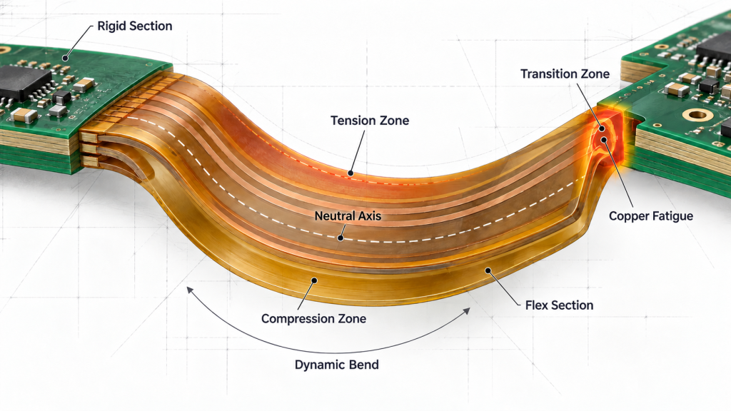
Copper is ductile, but it does not tolerate unlimited deformation. During bending, material on the outside of the curve is placed under tension while material on the inside is compressed. Between them is a region where longitudinal strain is lower, commonly described as the neutral axis.
Copper positioned farther from this neutral region experiences more strain during every bend. A thicker or more complex flex PCB stackup increases the distance between its outer conductive layers and the center of the structure. This is one reason why adding flexible copper layers can reduce dynamic life even though it provides additional routing capacity.
Copper thickness also creates a tradeoff. Heavy copper supports higher current and lowers conductor resistance, but it makes the flexible section harder to bend. If the mechanical system forces a thick conductor through a small movement path, copper fatigue can develop near the point of greatest curvature.
The foil type matters as well. Rolled annealed copper is often preferred in demanding dynamic applications because its elongated grain structure can provide better resistance to repeated flexing than electrodeposited copper. Material selection must still be coordinated with copper thickness, bend direction and the required number of cycles.
Trace geometry can intensify or distribute mechanical strain. Conductors should normally cross the bend region in a smooth and consistent direction. Sharp corners, abrupt width changes and local copper discontinuities can create stress concentration. Curved routing is generally more suitable than angular routing through a dynamic bend.
Large solid copper areas can make one part of the flex section significantly stiffer than another. When the assembly moves, the circuit may stop bending gradually and instead form a crease beside the rigid copper boundary. Hatched copper or carefully shaped conductors may provide a more uniform mechanical response where shielding or grounding is required.
The different conductors should also be distributed across the available width rather than stacked directly above one another without review. Vertically aligned traces can produce locally stiff regions, especially in multilayer constructions. Staggering their positions may help the flex area bend more evenly.
Dynamic reliability is therefore controlled by the complete relationship between copper type, copper thickness, layer count, conductor geometry and movement. Increasing bend radius alone cannot correct every weak structure in rigid flex circuit boards.
The Transition Zone Often Fails First
The rigid flex transition zone is where the flexible structure enters the rigid section. Material thickness and stiffness change rapidly at this boundary, making it one of the most mechanically sensitive regions of the circuit.
If the product allows bending to begin directly at the rigid-board edge, strain becomes concentrated in a narrow area. The flexible circuit may crease against the rigid material instead of forming a gradual curve. Copper conductors passing through this point then experience repeated deformation at nearly the same location.
Coverlay, adhesive and rigid-board materials can end at different positions in the transition. Poorly controlled overlap or abrupt thickness changes may further concentrate stress. The risk increases when plated holes, component pads, copper-plane edges or trace-width changes are placed too close to the boundary.
Routing should pass through the transition smoothly. Conductors that change direction immediately after leaving the rigid section are more exposed to fatigue because the electrical and mechanical transitions occur in the same area.
The product structure should also prevent the bend from migrating into the transition zone. A suitable support, formed shape or controlled free length can move the active bending region away from the rigid edge. This is usually more reliable than depending on the operator to position the flex correctly during every assembly.
Damage in this area may not create an immediate open circuit. A conductor can develop a small crack that remains electrically connected while stationary. Movement, temperature change or vibration then opens the crack temporarily, producing a fault that disappears when the product is inspected in a different position.
Stackup Decisions Change Flexibility
A flexible section containing one or two copper layers behaves differently from one containing several conductive and adhesive layers. Increasing layer count raises thickness and stiffness, making it more difficult for the circuit to follow a compact dynamic movement.
This does not mean that every rigid-flex product should use the minimum possible number of layers. Signal integrity, current capacity, grounding and electromagnetic compatibility may require additional copper. The important point is to avoid carrying unnecessary rigid-board layer construction through the active bend.
Rigid flex circuit boards can use different stackup zones so that the rigid areas provide routing density while the moving section remains thinner. These zones must be defined clearly in the fabrication data because coverlay, bonding layers and copper termination positions affect both manufacturing and mechanical performance.
The flexible dielectric and adhesive system also influences stiffness, thermal behavior and resistance to delamination. Material values should not be selected independently from the intended movement or manufacturing process.
The Product Must Control the Motion
A flexible circuit should not be allowed to find its own bend location inside an enclosure. Without mechanical control, repeated movement can create a small-radius fold, twisting or contact with a sharp housing edge.
Bending and twisting at the same time is particularly damaging because conductor strain becomes difficult to distribute predictably. A design validated under a simple planar bend may fail when the actual assembly introduces torsion.
The enclosure should establish the available flex length, movement direction and end positions. It should also prevent the flexible section from rubbing against screws, metal edges or nearby components.
For rigid flex circuit boards installed in hinges or sliding structures, motion should be evaluated across the complete travel range. The most severe condition may occur at an intermediate position rather than at either endpoint. A 3D mechanical review can reveal when the flex changes curvature or contacts another part of the assembly.
Functional Testing Does Not Prove Flex Life
A completed circuit may pass continuity and functional testing before any fatigue damage exists. These tests confirm present electrical performance but do not demonstrate that the conductors will survive the required movement.
Bend cycle testing should reproduce the actual displacement, bending direction and operating speed of the product. If the application experiences temperature changes, representative cycling may need to occur at more than one temperature because material stiffness and expansion behavior change with the environment.
Electrical continuity should be monitored while the circuit is moving. A crack may interrupt the signal for only a short period and reconnect when the circuit returns to rest. Measuring continuity only before and after the test can miss this intermittent failure.
After cycling, inspection should concentrate on the rigid flex transition zone, conductor-direction changes and areas where the flex developed a visible crease. Resistance changes, coverlay damage or local delamination may indicate that the structure is approaching failure even if a complete open circuit has not occurred.
IPC-2223 provides design requirements for flexible and rigid-flexible printed boards, while IPC-6013 addresses their qualification and performance. These standards provide the framework, but the test profile must still reflect the movement expected in the actual product. IPC standards revision information
Manufacturing Data Must Describe the Intended Movement
Gerber data shows the circuit geometry but does not explain how the product will move. The fabrication package should identify whether the flexible area is static or dynamic, where bending is permitted and which regions must remain free from repeated deformation.
The intended installed shape is also useful. It helps the manufacturer assess layer transitions, coverlay boundaries, copper construction and stiffener placement against the real mechanical condition.
When rigid flex circuit boards operate under repeated motion, iPCB can review the flex stackup, copper structure, transition zones and manufacturing data against the intended movement before fabrication. This connects the product’s mechanical requirements with the processes used to manufacture and inspect the circuit.
Repeated Motion Must Be Built Into the Structure
Rigid flex circuit boards do not achieve dynamic reliability simply because part of the assembly is flexible. Copper type, layer position, transition-zone geometry and product movement determine how much strain reaches each conductor.
A circuit folded once during installation may use a structure that is unsuitable for continuous bending. Conversely, a dynamic flex section requires its movement path and expected cycle life to be considered before the stackup and routing are finalized.
When the mechanical motion is defined, the flex region is kept appropriately thin and the real assembly is monitored during cycle testing, rigid flex circuit boards can maintain stable electrical connections throughout the intended product life.