Circuit board connectors carry power, signals and data between a PCB and the rest of an electronic system. A connection may work normally during final inspection but later become intermittent when the product experiences vibration, temperature changes or repeated mating cycles.
The reliability of circuit board connectors depends on two separate interfaces. The mating contacts must maintain stable electrical contact, while the connector terminals must remain securely attached to the PCB. A failure at either interface can produce voltage drop, communication errors, unexpected resets or complete loss of function.
A Connector Contains Two Electrical Interfaces
When a plug enters a receptacle, spring contacts apply force against the mating terminals. This force breaks through light surface films and creates small conductive contact areas.
Current then travels from the mating contact through the connector terminal and into the PCB solder joint. A connector can therefore have a stable solder joint but an unreliable mating interface. It can also have clean contacts while movement gradually damages the connection to the PCB.
Diagnosing circuit board connectors requires the complete path to be evaluated. Testing continuity only at the connector pins may not reveal whether resistance is changing at the contact surface or inside a mechanically stressed solder joint.
Contact Force Controls Electrical Stability
Connector contacts do not conduct across their entire visible surface. Electrical current passes through microscopic points where the metal surfaces touch. Stable contact resistance consequently depends on contact force, surface condition and plating integrity.
If the normal force is too low, vibration or thermal expansion can cause small movements between the contacts. These movements disrupt the conductive contact points and allow surface films to form.
Excessive mating force creates a different problem. It can damage the plating, deform the contact spring or make the connector difficult to assemble. Reliable circuit board connectors need enough normal force to maintain contact without exceeding the mechanical limits of the terminal system.
Fretting Corrosion Creates Intermittent Contact
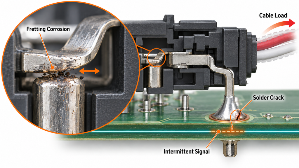
Fretting occurs when two mated contacts move by a very small amount. The movement may be caused by vibration, cable loads or the different thermal expansion of the connector housing, terminals and PCB.
Repeated motion removes part of the contact finish and exposes the underlying metal. Oxidized wear debris can then collect at the interface, increasing contact resistance. Because the debris moves during operation, the failure may appear and disappear when the connector is touched.
Tin-plated circuit board connectors are particularly dependent on stable contact force and controlled movement. Connector manufacturers use contact-spring geometry, suitable plating and secure housings to reduce relative movement. TE Connectivity, for example, describes contact systems designed to absorb vibration and thermal movement to limit fretting corrosion.
Gold plating provides better resistance to oxidation, but its thickness and underlying nickel barrier must match the expected mating cycles and environment. A thin decorative gold layer should not be treated as equivalent to an engineered contact finish.
Mechanical Loads Reach the PCB
A cable can transfer pulling, twisting and vibration directly into the connector body. If the connector relies only on its signal pins for mechanical support, these forces also reach the solder joints and PCB pads.
This is especially important for edge-mounted USB, power and communication connectors. Repeated cable insertion creates leverage at the board edge. A visually acceptable solder joint may gradually crack, or the copper pad may begin separating from the laminate.
Reliable circuit board connectors often use mounting tabs, through-hole stakes, shell connections or external strain relief to carry mechanical loads. These features allow the electrical terminals to conduct current without serving as the connector’s only structural support.
Enclosure alignment matters as well. If the connector opening and PCB are not correctly aligned, every cable insertion can push the connector sideways. The resulting failure originates from the mechanical assembly even though the damage eventually appears at the solder joint.
Solder Joint Formation Determines Board Attachment
Through-hole connectors require adequate barrel fill and proper wetting around the terminal. High copper mass or heavy ground connections can remove heat from the joint, causing incomplete solder flow.
Surface-mount connectors introduce different risks. Their terminals must remain coplanar with the PCB pads, and the solder-paste deposit must provide enough volume without creating bridges. Large mechanical tabs may require a different paste opening from the signal contacts.
For circuit board connectors with hidden terminals or shield joints, ordinary visual inspection may not reveal every defect. AOI can evaluate visible solder fillets and component position, while X-ray inspection may be required when important joints are located beneath the housing.
Surface contamination and damaged plating can also cause solder de-wetting. IPC describes de-wetting as a condition in which molten solder withdraws from the component or PCB surface, leaving a weak or incomplete intermetallic connection. Cleaning and storage conditions must therefore protect both connector terminals and PCB pads before assembly.
Electrical Loading Changes the Failure Consequences
A small increase in contact resistance may have little immediate effect on a low-current signal but can create significant heating in a power connection. As temperature rises, contact surfaces and connector housings can deteriorate further, accelerating the failure.
Current ratings should therefore be evaluated for the number of simultaneously loaded contacts, ambient temperature, PCB copper area and permitted temperature rise. The maximum current printed in a connector catalogue may be based on test conditions that differ from the final enclosure.
High-speed circuit board connectors introduce additional concerns. Contact geometry, pin assignment, return paths and unmated stubs can affect impedance and crosstalk. A connector may pass a DC continuity test while degrading a high-speed interface.
Connector Selection Must Match the Operating Environment
Pitch and pin count are not sufficient selection criteria. The expected vibration level, humidity, temperature range, mating frequency, current per contact and cable load all influence the appropriate connector family.
A connector used once inside a sealed consumer product has different requirements from one disconnected every day in industrial equipment. Likewise, a board-to-board connector inside a stationary enclosure should not automatically be used in a product exposed to vehicle vibration.
The qualification plan for circuit board connectors should reflect the actual application. IPC publishes connector test methods covering contact resistance, durability, humidity, insulation resistance, mechanical shock, vibration, thermal shock and fretting corrosion. Not every product requires every test, but the selected tests should reproduce the dominant field stresses.
Testing Must Detect Temporary Interruptions
A basic continuity test can miss a connection that opens for only a fraction of a second. During vibration or cable movement, this short interruption may be long enough to reset a processor or corrupt communication.
Testing circuit board connectors should therefore monitor continuity dynamically while mechanical stress is applied. Contact resistance should be measured before and after environmental exposure, rather than only checking whether the circuit remains open or closed.
For power connectors, testing should include voltage drop and temperature rise under realistic load. For communication connectors, functional traffic should pass through the interface during movement or thermal cycling. Repeated mating tests are appropriate when the connector will be serviced throughout the product’s life.
Production Control Must Cover the Complete Connection
Incoming inspection confirms the correct connector part number, plating and terminal condition. Assembly inspection verifies placement and solder formation. Functional testing then confirms that the complete interface carries its intended power or signal.
Forcircuit board connectors entering volume production,iPCB can combine component verification, solder-paste inspection, AOI, X-ray inspection and functional testing according to the connector structure and application environment. Mechanical support and enclosure alignment should also be reviewed before the PCBA process is finalized.
Reliable Connections Require Mechanical and Electrical Control
Intermittent connector faults are rarely solved by checking continuity alone. The contact surface, spring force, plating, housing retention, solder joint, PCB pad and enclosure all influence the same electrical path.
When circuit board connectors are selected for the real operating environment and supported by controlled assembly and dynamic testing, the risk of field failures falls significantly. The result is not merely a connector that works after assembly, but an interconnection that remains stable during the full service life of the product.