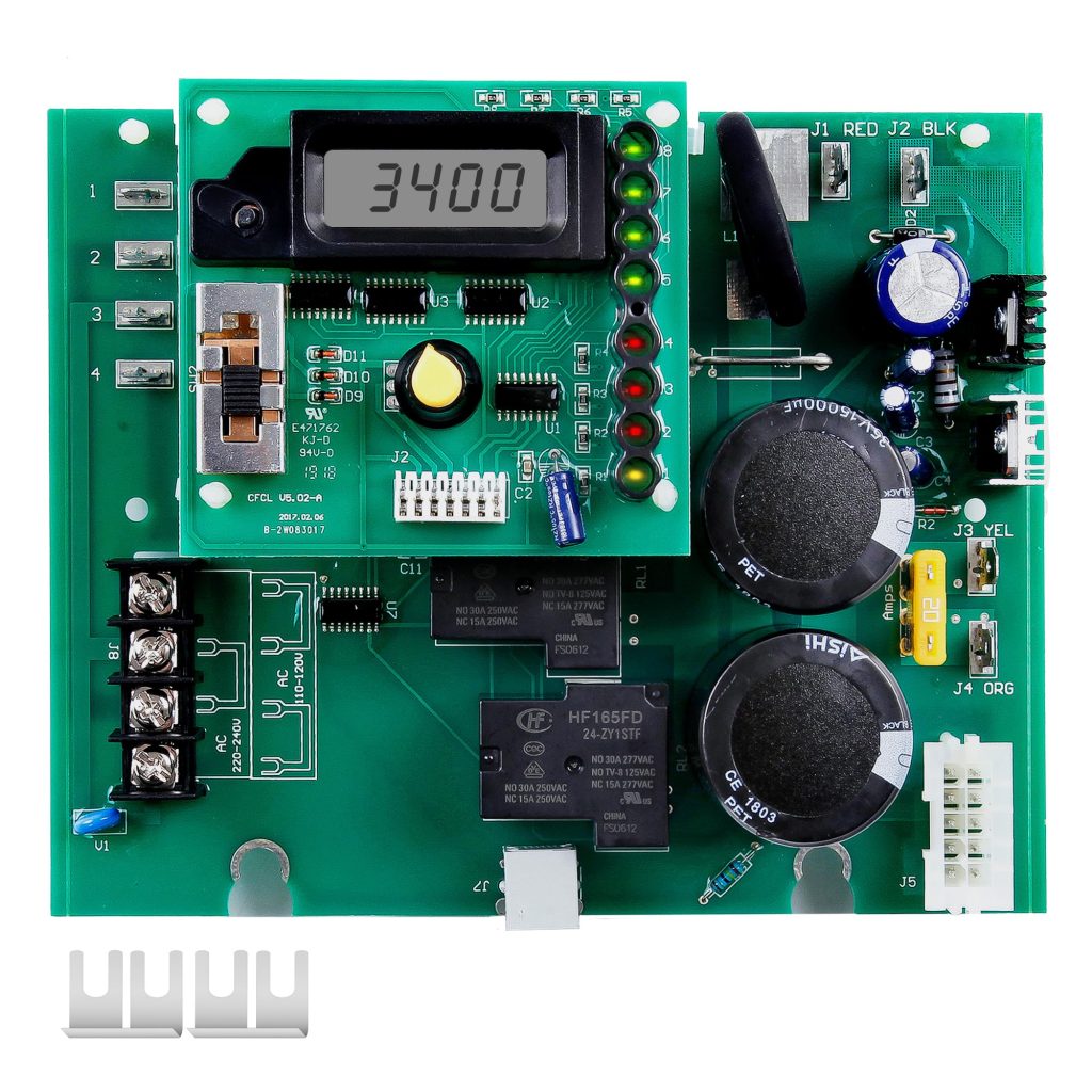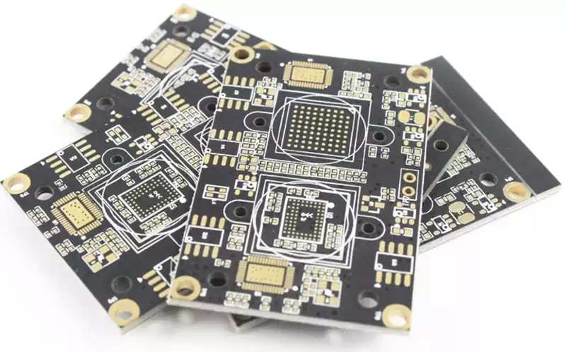
A circuit test board provides a practical way to access electrical connections, apply test signals, and evaluate circuit behavior during development or manufacturing. Depending on the application, the term may refer to a board designed specifically for testing, a circuit board under test, or a dedicated interface used to connect a device to test equipment. Understanding this distinction is important because test access, fixture design, and measurement requirements vary with the purpose of the board. A reliable circuit test board setup makes faults easier to identify and helps engineers obtain consistent results across repeated tests.
The Purpose of a Circuit Test Board
Testing can take place at several stages of electronic product development. During prototype debugging, engineers may need to measure supply voltages, observe waveforms, check communication signals, or isolate unexpected behavior. During manufacturing, testing helps verify that assembled boards contain the correct components and electrical connections. In some applications, a dedicated circuit test board or interface board connects the device under test to instruments, control systems, or automated test equipment.
The required approach depends on what needs to be verified. A bare PCB electrical test checks conductive paths for continuity and isolation. In-circuit testing (ICT) evaluates component values and connections on an assembled board through accessible electrical nodes. Functional testing checks whether the powered assembly performs its intended operation under defined conditions. These methods serve different purposes, so a test strategy should identify the target faults before selecting equipment or designing a fixture.
A useful test setup also separates the pcb board being evaluated from the hardware used to test it. The test fixture provides mechanical positioning and electrical contact, while the test program defines the measurements, expected values, and pass-or-fail limits. Keeping these roles clear helps prevent gaps in test coverage.
Test Access Must Be Planned During PCB Layout
A test system can only measure the electrical nodes it can reach. For this reason, test access should be considered during schematic development and PCB layout rather than added after routing is complete. Engineers should identify which power rails, ground connections, reset signals, communication lines, and critical analog nodes need to be measured or controlled.
Accessible test pads provide defined contact points for probes, oscilloscopes, multimeters, and automated fixtures. Their size and spacing must match the selected probe type and the positional accuracy of the test equipment. Pads should remain clear of components, connectors, and other physical obstructions. Depending on the testing process, access may be required from one side of the board or both.
Signal integrity also matters. A test pad or its connecting trace can add parasitic capacitance and inductance, potentially affecting sensitive high-speed signals. Test access should therefore be designed around the measurement objective rather than added indiscriminately. Where direct probing is unsuitable, engineers may need a dedicated connector, a different test method, or an alternative measurement point.
Good documentation completes the layout work. A test-point list should identify each location, its associated net, its purpose, and any relevant electrical limits. This information helps align the PCB design with the test fixture and the test program.

Fixture Design and Measurement Reliability
When repeated testing is required, a dedicated fixture can position the circuit board consistently and establish reliable electrical contact. Common arrangements use spring-loaded probes that press against designated pads, while other systems use connectors, cables, or custom interfaces. The choice depends on production volume, board geometry, required test coverage, and the complexity of the measurements.
Mechanical stability is essential. If the board shifts during testing or bends under probe pressure, contact resistance may vary and measurements may become inconsistent. The fixture must support the board adequately, maintain probe alignment, and avoid loading fragile components or connectors. Probe wear, contamination, and damaged contact surfaces should also be considered when assessing long-term repeatability.
Electrical performance requires equal care. Test leads and fixture wiring can introduce resistance, capacitance, inductance, or unwanted coupling. These effects may influence low-level analog measurements, high-current tests, and fast signal transitions. Ground references, cable routing, contact ratings, and instrument configuration should all suit the measurement being performed.
A well-designed circuit test board arrangement is therefore more than a collection of test pads. It is a coordinated interface between the board, fixture, instruments, and test procedure, with each part contributing to measurement accuracy.
Validate the Test Process Before Production
Before a test process is released, engineers should verify that it detects the faults it is intended to find. This includes confirming the electrical connections, checking measurement limits, testing known-good assemblies, and evaluating representative failure conditions where practical. A board that passes a test is not necessarily free of every possible defect; the result only demonstrates compliance with the checks included in that test procedure.
Test coverage should be reviewed alongside production requirements. ICT may be effective for checking component-level assembly faults, while functional testing is needed to evaluate overall operation. Flying-probe testing can provide flexible access without a dedicated bed-of-nails fixture, although test time and achievable coverage depend on the board and test requirements. No single method is suitable for every design.
Revision control is also important. Changes to PCB layout, component selection, firmware, or fixture wiring may affect expected measurements. Test documentation and programs should match the released board revision, and production results should be traceable when fault analysis or process improvement is required.
Ultimately, a dependable circuit test board strategy combines accessible test points, suitable fixture mechanics, appropriate measurement methods, and clearly defined acceptance criteria. Planning these elements early makes troubleshooting more efficient, improves test repeatability, and supports more consistent verification throughout electronic product development and manufacturing.