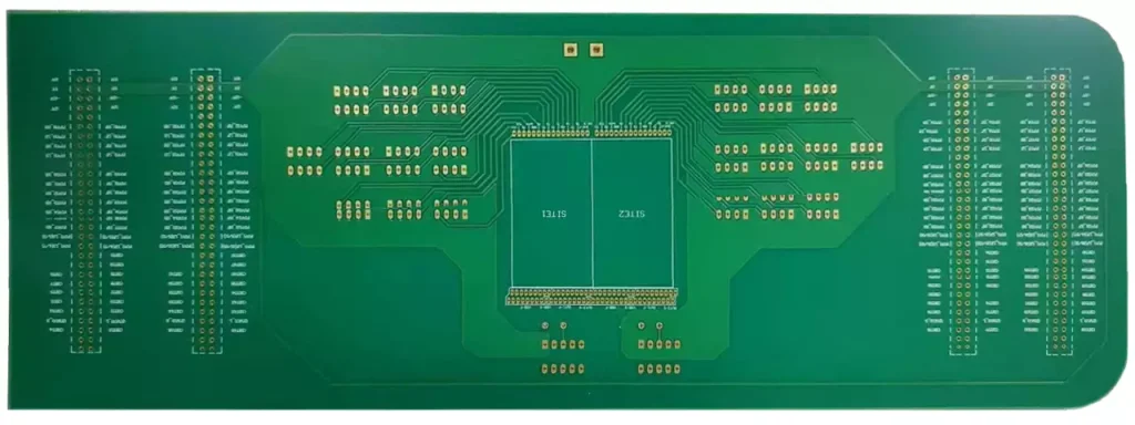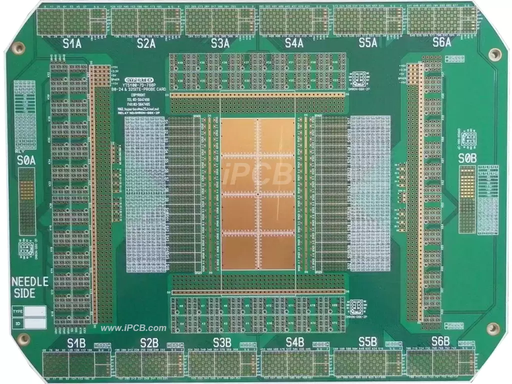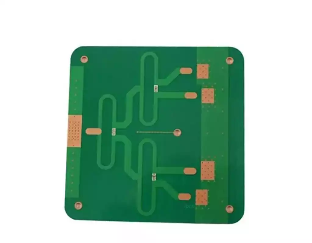
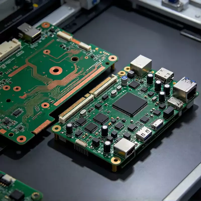
Circuit card assemblies are essential building blocks in modern electronic equipment. They consist of a fabricated printed circuit board populated with electronic components that work together to perform specific electrical functions. Unlike a bare PCB, which provides conductive pathways and mounting locations but has no installed components, a completed circuit card assembly contains the devices, connections, and supporting structures needed to operate as part of an electronic system.
The term circuit card assembly (CCA) is commonly used in industries such as aerospace, defense, telecommunications, and industrial electronics. It generally refers to an assembled circuit board and is closely related to the term Printed Circuit Board Assembly (PCBA). Although the terminology may vary between industries and manufacturers, the essential concept remains the same: a PCB becomes a functional assembly after the required components have been mounted, soldered, and verified.
The performance of circuit card assemblies depends on how well the board design, component selection, assembly process, and inspection requirements work together. A reliable assembly must provide stable electrical connections while meeting the mechanical, thermal, and environmental conditions expected during operation.
From Bare PCB to a Functional Circuit Card Assembly
The foundation of every circuit card assembly is the bare printed circuit board. Its substrate provides mechanical support and electrical insulation, while copper traces, pads, and vias establish the connections between different parts of the circuit. Depending on the application, the board may use a single-layer, double-sided, or multilayer construction. More demanding designs may require high-frequency materials, HDI structures, rigid-flex technology, or specialized thermal management solutions.
Electronic components are selected according to the circuit’s intended function and operating requirements. Resistors and capacitors control electrical characteristics, filter signals, and stabilize power supplies. Integrated circuits process information or control system behavior, while transistors, diodes, connectors, and other devices provide switching, protection, and external interfaces. Their arrangement on the PCB determines how electrical signals and power move through the completed assembly.
The connection between each component and the PCB must be mechanically secure and electrically reliable. Solder joints provide this connection, making soldering quality an important factor in overall assembly performance. Component footprints, pad dimensions, board thickness, copper design, and soldering conditions must therefore be considered together during product development.
Some circuit card assemblies also include additional features such as shielding, heat sinks, firmware, conformal coating, or protective enclosures. These requirements depend on the operating environment and the intended application. For example, an assembly installed in industrial equipment may need protection against dust, moisture, and vibration, while a high-frequency communication board may require carefully controlled impedance and electromagnetic compatibility.
How Circuit Card Assemblies Are Manufactured and Verified
Manufacturing begins with the engineering information required to produce the board and assemble its components. This usually includes PCB fabrication data, a bill of materials, component placement files, assembly drawings, and relevant process instructions. Before production starts, these documents should be reviewed for consistency. Incorrect component specifications, missing footprints, or mismatched design revisions can create problems that become more difficult and expensive to correct after assembly.
For circuit boards using surface-mount technology, solder paste is applied to the designated pads through a stencil. Automated placement equipment then positions components according to the placement data, followed by reflow soldering under a controlled temperature profile. Components with leads inserted through drilled holes may be installed using through-hole technology and soldered through wave soldering, selective soldering, or other suitable methods. Many electronic products combine SMT and through-hole processes to accommodate different component packages and mechanical requirements.
The circuit card assembly process needs to account for component sensitivity, PCB construction, and the thermal characteristics of the materials involved. Excessive heat, unsuitable soldering conditions, or poor component placement can affect connection quality and potentially damage sensitive devices. Consistent process control helps maintain solder joint quality and reduces variations between production batches.
Inspection and testing follow assembly to determine whether the finished pcb board meets its defined requirements. Automated optical inspection can identify visible issues such as missing components, incorrect orientation, placement deviations, and certain soldering defects. For packages with hidden connections, such as many BGA devices, X-ray inspection can provide information that ordinary visual inspection cannot obtain.
Electrical and functional testing provide further verification. In-circuit testing can check selected electrical connections and component characteristics, while flying probe testing may be suitable for prototypes and lower-volume production. Functional testing evaluates whether the assembly performs its intended operations under specified input and operating conditions. The appropriate testing strategy depends on circuit complexity, product risk, production volume, and customer requirements.
Reliability and Manufacturing Requirements OF Circuit Card Assemblies
The reliability of circuit card assemblies is influenced by more than the quality of their solder joints. Component ratings, PCB material properties, electrical loading, heat dissipation, mechanical support, and environmental conditions all affect long-term performance. A board designed for a temperature-controlled indoor environment may not be suitable for equipment exposed to repeated thermal cycling, vibration, humidity, or electrical transients.
Thermal management deserves particular attention in assemblies containing power devices, processors, or other components that generate significant heat. Copper planes, thermal vias, suitable substrate materials, and heat sinks can help control temperature distribution. At the same time, engineers need to consider the thermal limits of components and solder connections to avoid creating localized overheating or excessive thermal stress.
Mechanical reliability is equally important. Heavy components, connectors, and parts positioned near board edges may experience additional stress during operation or handling. Appropriate mounting arrangements, board support, and connector selection can reduce the likelihood of mechanical damage. For products operating in harsh environments, conformal coating or other protective measures may also be specified, provided that they are compatible with the components and subsequent servicing requirements.
Manufacturing standards help establish consistent workmanship and inspection criteria. IPC J-STD-001 defines requirements for soldered electrical and electronic assemblies, while IPC-A-610 provides acceptance criteria for completed electronic assemblies. The applicable standard, product class, and revision should be agreed upon before manufacturing rather than assumed to be identical for every project.
Clear documentation is another part of reliable production. The PCB revision, component list, assembly drawings, inspection criteria, and test procedures should describe the same product configuration. When a component is replaced or a layout is revised, the relevant documents need to be updated together. This allows manufacturers and customers to trace production changes and maintain consistency across different batches.
When sourcing circuit card assemblies, it is also important to define the actual scope of manufacturing. Some projects require only component placement and soldering, while others include PCB fabrication, component procurement, programming, functional testing, conformal coating, and final integration. Clarifying these requirements before requesting a quotation helps avoid differences in expectations between the buyer and manufacturer.
Ultimately, circuit card assemblies transform PCB designs into working electronic units through the coordinated selection of materials, components, manufacturing processes, and verification methods. When these elements are properly managed, the completed assemblies can meet their intended electrical, mechanical, and environmental requirements while providing a dependable foundation for the larger electronic system.