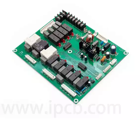
Custom PCB assembly involves mounting and soldering electronic components onto a printed circuit board according to a specific circuit design and production requirement. Unlike standard assembly services that follow fixed configurations, custom PCB assembly is organized around the customer’s component selection, board layout, assembly method, quality requirements, and intended application. Whether a project involves a small prototype run or a larger production order, the assembly process needs to account for component availability, soldering requirements, manufacturing tolerances, and inspection procedures.
The requirements can vary considerably from one project to another. A compact consumer electronic device may rely primarily on surface-mount components, while an industrial control board may combine SMT components with larger through-hole parts. Some products also require fine-pitch packages, BGA components, specialized connectors, or additional testing before they can be released for use. These differences influence how the PCB is prepared, assembled, inspected, and tested.
A bare PCB provides the conductive pathways and physical structure of an electronic circuit, but it cannot perform its intended function until the required components are installed. PCB assembly, commonly referred to as PCBA, is the process of placing and soldering those components onto the board.
Custom PCB assembly follows the specifications of an individual project rather than relying on a standard component configuration. The customer typically provides the PCB design files, bill of materials (BOM), assembly drawings, and other production information. The manufacturer uses these documents to prepare the board, source or receive the components, program assembly equipment, and complete the required soldering and inspection processes.
The level of customization depends on the product. A relatively simple board may require only standard SMT placement, while a more complex design could involve mixed-technology assembly, fine-pitch components, BGA packages, selective soldering, or additional functional testing. The assembly process should be selected according to the actual component packages and electrical requirements rather than applying the same production method to every board.
Custom PCB Assembly and Bare PCB Manufacturing Are Different Processes
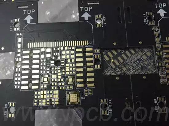
Bare PCB manufacturing and PCB assembly are closely related, but they serve different purposes. Bare PCB fabrication produces the physical circuit board, including its copper patterns, insulating layers, plated holes, solder mask, and surface finish. PCB assembly begins after the board has been fabricated and involves installing the electronic components that make the circuit operational.
These processes require different equipment, materials, and quality checks. PCB fabrication focuses on features such as layer registration, trace geometry, drilling accuracy, copper plating, and electrical continuity. Assembly places greater emphasis on component positioning, solder joint quality, polarity, soldering temperature, and electrical functionality.
A customer can purchase bare PCBs from one manufacturer and arrange assembly separately, or work with a supplier that provides both PCB fabrication and assembly. Using one supplier for both stages can simplify coordination because the fabrication and assembly teams can review the board design together. However, the suitability of this arrangement depends on the supplier’s actual capabilities and the requirements of the project.
SMT and Through-Hole Assembly
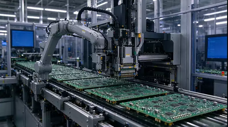
Surface-mount technology (SMT) is widely used in modern PCB assembly because it allows components to be mounted directly onto the surface of the board. Components are typically placed using automated pick-and-place equipment, with solder paste applied to the designated pads before the board passes through a reflow oven.
SMT supports compact layouts and high component density, making it suitable for products where board space is limited. It is commonly used for resistors, capacitors, integrated circuits, connectors, and many other electronic components. The process can also support fine-pitch packages, although these require accurate solder paste printing, component placement, and thermal control.
Through-hole technology uses component leads that pass through drilled holes in the PCB. The leads are soldered to pads on the opposite side or within the board structure, creating mechanical and electrical connections. Although SMT has replaced through-hole assembly in many applications, through-hole components remain useful for connectors, larger components, and parts that require stronger mechanical attachment.
Some PCB designs combine both technologies. This is known as mixed-technology assembly, and it requires careful planning because the order of component placement and soldering can affect the production process. The assembly method should account for component dimensions, soldering requirements, board layout, and the thermal characteristics of the selected parts.
The Main Stages of a Custom PCB Assembly Process
The pcb assembly process begins with a review of the customer’s production files. These usually include Gerber or ODB++ data, a BOM, pick-and-place files, and assembly drawings. The manufacturer checks whether the information is consistent and complete before preparing the production line.
The BOM is particularly important because it identifies the components required for the board, including part numbers, descriptions, quantities, package information, and approved alternatives where applicable. If a component is obsolete, unavailable, or listed with an unclear part number, the issue should be resolved before assembly begins. Otherwise, incorrect substitutions or sourcing delays may affect the production schedule.
Once the documentation has been reviewed, the bare PCBs and electronic components are prepared for production. For SMT assembly, solder paste is deposited onto the PCB pads through a stencil. The stencil openings determine where the paste is applied, so its design and alignment have a direct effect on solder joint quality.
The pick-and-place machine then positions the components according to the placement data. Component orientation, polarity, package dimensions, and placement accuracy must all match the assembly documentation. After placement, the board passes through a reflow oven, where a controlled temperature profile melts the solder paste and forms the electrical and mechanical connections.
Through-hole components may be installed manually or with suitable automated equipment, depending on their quantity, package type, and production requirements. Wave soldering and selective soldering are two methods used for different through-hole assembly applications. Selective soldering is particularly useful when only specific areas of a mixed-technology board require through-hole soldering and nearby SMT components must be protected from excessive heat.
After soldering, the assembled PCB undergoes inspection and any required rework. Cleaning may also be necessary depending on the soldering materials and product requirements. The finished assembly is then prepared for electrical testing, packaging, and delivery.
Component Sourcing and BOM Management
Component sourcing can have a significant effect on the cost and schedule of a custom PCB assembly project. Even when the PCB design is complete, production may be delayed if important components are unavailable or if the BOM contains incomplete or inaccurate information.
A reliable sourcing process should begin with the exact manufacturer part numbers specified by the customer. Package type, electrical ratings, tolerance, operating temperature, and other relevant characteristics need to be checked before a component is purchased or substituted. Two components may appear similar but have different electrical specifications or footprints, so visual similarity is not enough to establish interchangeability.
Customers generally choose among three sourcing arrangements. In a turnkey project, the assembly provider is responsible for sourcing the components as well as assembling the PCB. In a consigned arrangement, the customer supplies all required components, while the manufacturer handles assembly. Partial turnkey projects combine the two approaches, allowing the customer to supply selected components while the manufacturer sources the remainder.
The most suitable option depends on purchasing arrangements, component availability, inventory management, and the customer’s control requirements. Regardless of the sourcing model, component substitutions should be reviewed and approved before they are introduced into production.
Design Considerations Before PCB Assembly
A PCB layout that can be fabricated successfully is not necessarily ready for efficient assembly. Component spacing, pad geometry, solder mask openings, board edges, fiducial marks, and component orientation all influence how reliably the assembly equipment can process the design.
Design for Manufacturing (DFM) and Design for Assembly (DFA) reviews help identify these issues before production. For example, components placed too close to one another may make automated placement or soldering difficult. Poorly positioned fiducial marks can affect machine alignment, while unsuitable pad dimensions may contribute to insufficient solder or solder bridging.
Thermal considerations also matter. Components with different thermal masses may require adjustments to the soldering profile, particularly when a board combines small SMT packages with larger connectors or through-hole parts. BGA components introduce additional inspection considerations because many of their solder joints are hidden beneath the package.
Reviewing the assembly requirements during the PCB design stage can reduce production problems and avoid unnecessary changes after the board has been fabricated.
Inspection and Testing for Assembled PCBs
Inspection is an important part of PCB assembly because defects can affect electrical performance, product reliability, and the efficiency of later manufacturing stages. The appropriate inspection methods depend on component packages, board complexity, and the quality requirements of the finished product.
Automated Optical Inspection (AOI) uses cameras and image-processing systems to identify visible assembly defects. It can help detect missing components, incorrect polarity, misalignment, solder bridges, and other visible problems. However, AOI cannot directly inspect every hidden solder joint, so additional methods may be necessary for certain packages.
X-ray inspection is commonly used for BGA components and other solder joints that cannot be fully examined from the outside. It can reveal issues such as voiding, bridging, and insufficient solder connections beneath a package. The inspection criteria should reflect the component type and applicable acceptance requirements.
In-Circuit Testing (ICT) checks electrical connections and component characteristics through dedicated test points or fixtures. Functional testing goes a step further by evaluating whether the assembled board performs according to its intended operating requirements. These methods serve different purposes, and not every project needs all of them.
For products with specific reliability requirements, the inspection and testing plan should be agreed upon before production. Standards such as IPC-A-610 may be used to define acceptance criteria for electronic assemblies, while J-STD-001 addresses requirements for soldered electrical and electronic assemblies. The applicable class and requirements should be confirmed with the customer and manufacturer.
Prototype PCB Assembly and Volume Production
Prototype PCB assembly is generally used to verify a design before larger quantities are manufactured. It allows engineers to evaluate component placement, soldering quality, electrical behavior, thermal performance, and mechanical compatibility with the finished product.
During this stage, design changes are relatively common. A component may need to be replaced, a footprint adjusted, or a layout revised after testing reveals an issue. For that reason, prototype production often requires flexibility and close communication between the customer and assembly provider.
Volume production has different priorities. Once the design has been validated, the focus shifts toward repeatability, component availability, process stability, production yield, and consistent inspection. The assembly provider must also maintain accurate revision records so that boards from different production batches follow the correct design and BOM.
Moving from a prototype to regular production should involve a review of the final assembly documentation. Changes to component specifications, approved alternatives, soldering profiles, or inspection criteria should be controlled rather than introduced informally during manufacturing.
How to Choose a Custom PCB Assembly Manufacturer
Selecting a custom PCB assembly manufacturer requires an assessment of both technical capability and production management. A supplier may be able to assemble a basic SMT board but lack the equipment or experience needed for fine-pitch components, BGA packages, mixed-technology boards, or more demanding testing requirements.
Start by comparing the manufacturer’s assembly capabilities with the actual design. Relevant factors include supported component packages, minimum component size, placement accuracy, SMT and through-hole processes, soldering equipment, and available inspection methods. If the design includes specialized components, ask whether the supplier has experience processing those packages.
Component sourcing is another important consideration, particularly for projects with long lead times or components that are difficult to obtain. Ask how the manufacturer verifies part numbers, manages substitutions, and handles customer-supplied inventory. Clear procedures can help prevent component mix-ups and production delays.
Quality management, communication, and revision control also deserve attention. A suitable supplier should be able to explain its inspection process, identify potential assembly issues, and maintain traceability for materials and production batches where required. For ongoing projects, these capabilities can be just as important as the initial assembly price.
What Information Is Needed for a Custom PCB Assembly Quote?
An accurate quotation depends on how clearly the assembly requirements are defined. The manufacturer typically needs the PCB fabrication data, BOM, pick-and-place files, assembly drawings, and production quantity. Additional information may include approved component alternatives, assembly-side requirements, soldering specifications, testing procedures, and packaging instructions.
It is also important to clarify who is responsible for sourcing the components. If the customer supplies some or all of the parts, the quantities, delivery schedule, packaging condition, and inventory information should be confirmed before production. If the assembly provider handles sourcing, the BOM should include exact manufacturer part numbers and any approved alternatives.
Providing complete documentation at the beginning makes it easier to compare quotations and reduces the risk of misunderstandings during production. It also allows the manufacturer to identify missing information or potential assembly problems before the order is released.
Frequently Asked Questions
What is custom PCB assembly?
Custom PCB assembly is the process of installing and soldering electronic components onto a bare printed circuit board according to a specific design and production requirement. It can involve SMT, through-hole technology, or a combination of both.
What files are required for custom PCB assembly?
Most projects require PCB fabrication files, a BOM, pick-and-place data, and assembly drawings. The manufacturer may also need component specifications, approved alternatives, testing requirements, and packaging instructions.
What is the difference between PCB fabrication and PCB assembly?
PCB fabrication produces the bare circuit board, including its copper layers, insulation, vias, and surface finish. PCB assembly installs and solders electronic components onto that board to create a functional electronic assembly.
What is the difference between turnkey and consigned PCB assembly?
Turnkey PCB assembly means the manufacturer handles component sourcing and assembly. In consigned assembly, the customer supplies the components while the manufacturer performs the assembly work. Partial turnkey combines these arrangements.
Can custom PCB assembly include both SMT and through-hole components?
Yes. Many electronic products use mixed-technology assembly because different components have different mechanical and electrical requirements. The production sequence must be planned according to component packages and soldering methods.
Does every assembled PCB require AOI and X-ray inspection?
No. AOI is commonly used to inspect visible assembly features, while X-ray is particularly useful for hidden solder joints such as those beneath BGA packages. The required inspection methods depend on the board design, component types, and agreed quality criteria.
Can a PCB assembly manufacturer handle prototype and mass production orders?
Some manufacturers support both, but their production capabilities and minimum order requirements vary. It is worth confirming whether the supplier can maintain the same component specifications, assembly process, and quality standards as the project moves from prototype to volume production.
How can PCB assembly costs be reduced?
Costs can often be controlled by using readily available components, reducing unnecessary component variety, selecting practical package types, and providing complete manufacturing documentation. The design should also be reviewed for assembly issues before production to avoid additional setup, rework, or component replacement.
Custom PCB assembly brings together component sourcing, board preparation, placement, soldering, inspection, and testing. Each stage affects the quality of the finished electronic assembly, and the most appropriate production method depends on the design, component packages, order quantity, and intended application.