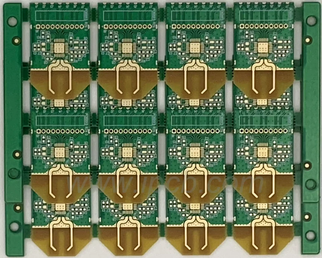
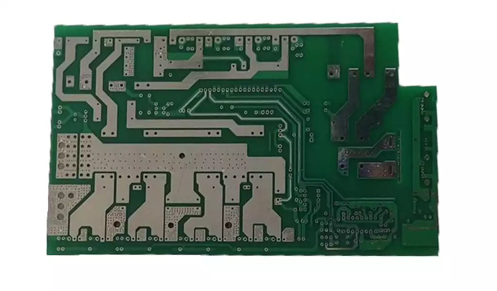
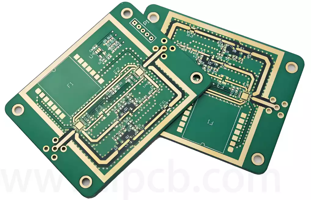
Circuit boards are an indispensable core part of modern electronic devices. They integrate various electronic components and realize various functions of the equipment through reasonable circuit design.
However, for beginners, identifying components on circuit boards can be a challenge. This article will introduce in detail how to identify components on circuit boards, from component classification, appearance characteristics to identification information and other aspects, to help readers quickly master relevant skills.
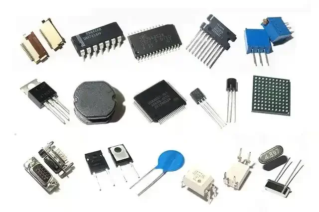
Classification of components on circuit boards
Before starting to identify components on circuit boards, it is very necessary to understand the classification of components. According to different functions and properties, components on circuit boards can be mainly divided into the following categories:
Passive components
Resistor: Controls the flow of current, common appearance is cylindrical or rectangular, and the surface usually has a color ring to identify the resistance value.
Capacitor: Stores charge, common forms include cylindrical aluminum electrolytic capacitors and small chip capacitors.
Inductor: Obstructs the change of current, usually in the shape of a coil, or a small square formed in one piece.
Active components
Diode: A unidirectional conductive component, common appearance is a small cylindrical shape with a silver mark on one end.
Transistor: used to amplify or switch signals, mostly in black or gray plastic package with three pins.
Integrated Circuit (IC): an electronic module that performs specific functions, with a black square or rectangular chip.
Connector Components
Connector: an interface that connects different circuit boards or devices, with various appearances, such as pin type and slot type.
Switch: used to connect or disconnect circuits, common types include toggle switches, push button switches, etc.
Other Components
Display devices (such as LED, LCD): used to display information or status.
Sound devices (such as buzzers): used to produce sound.
Through the above classification, we can have a preliminary understanding of the components on the circuit board.
How to identify components by appearance features
Each component has its own unique appearance features, through which we can preliminarily judge the type of component.
Resistors
Resistors are one of the most common components, and their characteristics include:
Axial resistors: cylindrical in appearance, with a color ring on the surface.
Chip resistors: small rectangular in appearance, with numbers or letters on the surface to indicate the resistance value.
Capacitors
The appearance features of capacitors include:
Aluminum electrolytic capacitors: cylindrical, usually with a depression on the top, marked with capacity and withstand voltage.
Ceramic capacitors: small discs or chip cuboids, no polarity marking.
Diodes
Diodes usually have a small cylindrical appearance, with a silver or white ring mark on one end to distinguish between positive and negative poles.
Integrated Circuits (ICs)
ICs are usually black rectangular or square plastic packages with model and manufacturer information marked on the surface. The number and arrangement of pins are its important features.
Connectors
Connectors have various appearances, and common types include:
Pin headers: multiple pins are neatly arranged.
Slots: rectangular or square, used to plug in other components.
Most components can be quickly identified by careful observation of the appearance of the components.
How to identify components by identification information
On a circuit board, each component usually has identification information. This identification information includes component number, model, parameters, etc., which is an important basis for identifying components.
Component number
Each component on a circuit board usually has a unique number, such as R1, C2, D3, etc. The meaning of the number is:
R stands for resistor (Resistor).
C stands for capacitor (Capacitor).
D stands for diode (Diode).
U stands for integrated circuit (IC).
Q stands for transistor (Transistor).
Model information
The surface of the component usually has a model printed on it, such as the resistance value of the resistor, the capacity of the capacitor, the model of the diode, etc. According to these models, you can find the corresponding technical parameters.
Parameter marking
Parameter marking refers to the electrical parameters directly marked on the surface of the component, for example:
Resistance value of resistor: usually indicated by color ring or number, such as 220Ω or 4.7kΩ.
Capacitance of capacitor: in uF (microfarad) or pF (picofarad), such as 10uF, 100pF.
Diode model: such as 1N4007.
Identification information is an important clue for component identification. By consulting the information, you can have a deeper understanding of the functions and characteristics of the component.
How to use tools to help identify components
Sometimes, visual observation alone may not be enough to accurately identify components. In this case, you can use some tools to assist in identification.
Multimeter
Measure the resistance value to determine the resistance.
Measure the capacitance of the capacitor.
Check the forward and reverse conduction of the diode.
Microscope or magnifying glass
For components with small size or unclear surface printing information, you can use a magnifying glass to observe.
Online databases and data manuals
According to the model on the surface of the component, find relevant information online, such as the specification sheet (Datasheet).
Technical details analysis
When identifying circuit board components, some technical details need special attention:
Package form
The package form of the SMD component, such as 0603, 0805, etc., directly affects its size. Reference manuals are needed for identification.
Plug-in components have different pin arrangements, such as direct plug-in and bent pin.
Polarity identification
Some components (such as electrolytic capacitors and diodes) have polarity, and their positive and negative poles are usually distinguished by markings.
The silver ring of the diode is the negative pole.
The long pin of the electrolytic capacitor is the positive pole, and the short pin is the negative pole.
Impact of the working environment
The environment in which the circuit board is located (such as high temperature and high humidity) will affect the appearance and performance of the components. For example, long-term high temperature may cause the top of the capacitor to swell or leak.
Future development trend of circuit board component identification
With the continuous advancement of electronic technology, the types and complexity of circuit board components are also increasing. The future component identification technology will show the following development trends:
Automated identification
Using image recognition technology, use cameras and AI algorithms to automatically analyze components on the circuit board. This will significantly improve the recognition efficiency, especially for quality inspection in mass production.
Intelligent tools
Future multimeters or testers may integrate AI functions to automatically identify the types and parameters of components. For example, a smart multimeter can not only measure the resistance value, but also display the power rating and temperature coefficient of the resistor.
Virtual reality assisted identification
Combined with AR technology, component information is directly marked on the circuit board by wearing a device. For example, a maintenance engineer can quickly locate a faulty component and its parameters through AR glasses.
Higher integration design
With the further reduction of component size and the integration of functions, the difficulty of identifying components may increase. For example, most of the components on modern mobile phone motherboards are ultra-small SMD devices, which require more sophisticated instruments to identify.
Improvement of education and training
To meet the needs of the industry, various colleges and training institutions will strengthen the teaching of component identification-related courses and use tools such as virtual laboratories to improve learning efficiency.
Summary
Through the introduction of this article, we have analyzed in detail how to identify components on circuit boards, including component classification, appearance characteristics, identification information, and auxiliary application of tools. Identifying circuit board components is a basic skill in electronic engineering. It not only helps beginners get started quickly, but also provides convenience for professionals to solve practical problems. In addition, we also look forward to the development trend of future identification technology, such as automation, intelligence, and virtual reality applications, which will further improve efficiency and reduce the difficulty of identification.
Whether it is by observing the appearance of components, interpreting identification information, or using tools such as multimeters and microscopes, mastering these methods is a key ability in the electronics industry. At the same time, with the development of science and technology, intelligent and automated equipment will gradually change the traditional component identification methods and promote the industry to develop in a more efficient and accurate direction.
I hope this article provides readers with a comprehensive guide that will be helpful in their daily work or study, and lay a solid foundation for further exploration in the field of electronic technology.
