In the fields of fault diagnosis, hardware repair, and industrial maintenance of modern electronic equipment, capacitors are among the electronic components with the highest failure rate. From bulging electrolytic capacitors in power adapters to short-circuiting miniature multilayer ceramic capacitors (MLCCs) on high-frequency communication motherboards, capacitor failure often paralyzes the entire circuit board.
However, desoldering capacitors from the circuit board for individual testing is not only time-consuming and labor-intensive, but also extremely prone to causing the thermal stress applied by the high temperature of the soldering iron to peel off the pads or break the inner layer traces of the multilayer printed circuit board (PCB). Therefore, “in-circuit testing,” which involves directly assessing the electrical performance and health status of capacitors on the circuit board without removing them, has become a core skill that hardware engineers and microelectronics repair experts must master.
how to test a capacitor on a circuit board?In-circuit testing of capacitors is far more than a simple multimeter measurement; it is a microscopic physical game involving distributed parameter isolation, high-frequency impedance characteristic analysis, the physical evolution of equivalent series resistance, and semiconductor junction voltage drop interference.
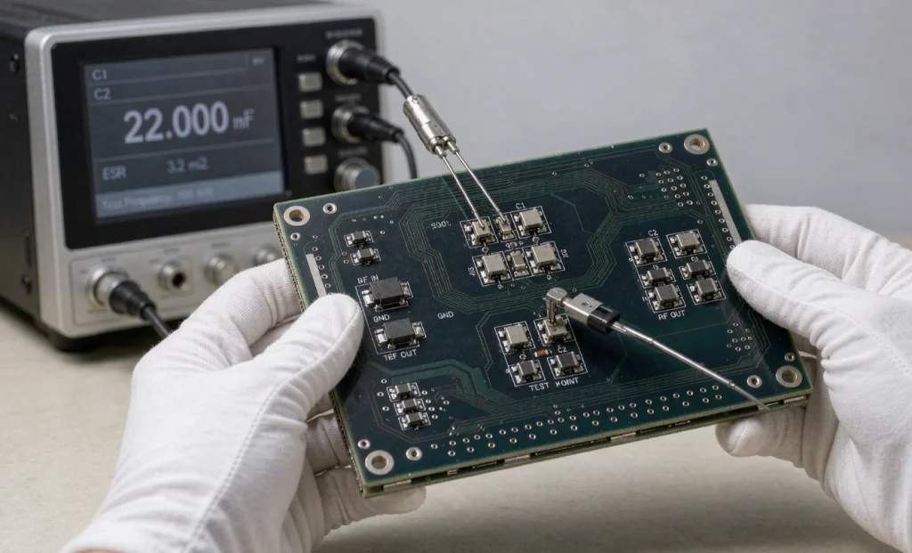
The Physical Nature of Capacitors and Their Failure Physics on Circuit Boards
To accurately test capacitors on a circuit board, it is essential to deeply understand the structural nature of capacitors in the real physical world and their failure evolution mechanisms in circuits.
From Ideal Capacitors to Non-Ideal Equivalent Models
In fundamental physics, a capacitor is simplified as an ideal element with two parallel conductive plates sandwiching an insulating dielectric layer. However, the physical structure of a capacitor operating on a real printed circuit board is far more complex.
A real capacitor must be physically considered as a complex network composed of multiple parasitic elements:
Main Capacitance: The energy storage core determined by the plate area, plate spacing, and dielectric constant of the dielectric.
Equivalent Series Resistance (ESR): The resistive loss determined by the resistance of the metal leads, the contact resistance between the plates and the dielectric, and the electrolyte ion mobility.
Equivalent Series Inductance (ESL): The parasitic inductance generated by the capacitor’s winding structure and the geometry of its physical leads.
Equivalent Parallel Leakage Resistance: The resistance corresponding to the tiny current leaking through the insulating dielectric.
At low frequencies, capacitors exhibit excellent DC blocking and AC passing characteristics; however, at high frequencies, parasitic inductance and capacitance resonate, and above the resonant frequency, the capacitor may even transform into an inductive element. This is why specific frequencies must be selected for board testing based on the testing objectives.
Three Core Physical Mechanisms of Capacitor Failure
During long-term operation of a circuit board, capacitors primarily experience three physical failures due to thermal stress, electrical stress, and chemical aging:
Hard Breakdown and Micro-Short Circuit: This is the most severe form of failure. When an overcurrent surge or electrostatic discharge penetrates the extremely thin insulating dielectric layer inside the capacitor, the insulating layer is physically broken down, forming a molten metal channel. In multilayer ceramic capacitors, when subjected to mechanical bending stress from the PCB, micro-cracks develop in the internal ceramic dielectric, causing metal electrode migration and ultimately leading to a direct connection between the two electrodes, manifesting as an absolute short circuit with extremely low resistance.
Dramatic Increase and Drying of Equivalent Series Resistance (ESR): This phenomenon is common in aluminum electrolytic capacitors. Electrolytic capacitors rely on a chemical electrolyte to maintain chemical equilibrium and a high dielectric constant. As equipment operates at high temperatures for extended periods, the electrolyte gradually evaporates and dries through the micropores of the rubber gasket. While the capacitance may still be within the nominal range when measured with a standard multimeter, its ESR value may have increased tens or even hundreds of times. This causes the capacitor to lose its ability to decouple at high frequencies and filter ripple, generating enormous self-heat, and even leading to excessive power supply ripple and frequent system restarts.
Capacitance decay and open circuit. Due to broken internal electrode solder joints, lead corrosion and detachment, or dielectric material polarization decay caused by prolonged high-voltage bias, the actual capacitance of the capacitor will be significantly lower than the nominal value, or even completely open-circuit.
The fundamental physical dilemma of on-board testing: Bypass effect and distributed network
Why is measuring capacitors on-board much more difficult than off-board? The root cause lies in the “bypass effect” brought about by the intricate electrical network on the circuit board.
Parallel topology’s shunting and masking of measurement signals
On a real circuit board, a capacitor is never isolated. It is typically mounted between the power plane and the ground plane, along with the chip’s power pins, resistors, inductors, and hundreds of other capacitors.
When the probes of a test instrument touch the two ends of the capacitor under test, the measurement current does not just flow through the capacitor but diffuses along all connected physical paths. For example:
If the capacitor under test is connected in parallel with a low-resistance resistor or inductor, most of the test current from the instrument will flow away from the resistor or inductor, causing the measurement result to be completely masked by the low-impedance component, exhibiting a false “short circuit” phenomenon.
If multiple capacitors of the same specification are connected in parallel to form a capacitor array (extremely common in the power supply area of CPU or GPU cores), the test instrument probes will measure the total superimposed capacitance of the entire array, making it impossible to directly identify a single capacitor with degraded capacitance from a single measurement.
Forward Conduction Interference of Semiconductor PN Junctions
Circuit boards are densely packed with integrated circuit chips, diodes, and transistors. These semiconductor components contain a large number of PN junctions.
A PN junction exhibits nonlinear unidirectional conductivity: when the forward voltage applied across it is below the conduction threshold (approximately 0.6 volts for a silicon PN junction), it exhibits high resistance; however, once the test voltage exceeds this threshold, the PN junction rapidly conducts, exhibiting extremely low impedance.
If the output signal voltage of the test instrument is higher than the conduction voltage of the semiconductor PN junction, current will penetrate the surrounding internal circuitry of the chip, creating extremely complex parasitic loops. This not only leads to complete distortion of measurement data, but the strong current may even damage sensitive microprocessor chips.
On-Board Testing Technology Evolution and Core Measurement Methods
To overcome bypass effects and PN junction conduction interference, the electronics engineering community has evolved several highly targeted on-board measurement techniques.
Low-Voltage Static Impedance and Initial Screening After Power-Off
Before performing any power-on test or precision impedance measurement, the circuit board must first be completely powered off, and the large-capacity capacitors in the area under test should be artificially discharged using a high-power resistor to prevent residual charge from burning out the test instrument.
With the power off, using the resistance or buzzer setting on a standard digital multimeter is the fastest way to find a “hard breakdown” short-circuited capacitor. To prevent the PN junctions inside surrounding chips from conducting, modern digital multimeters strictly limit the output voltage to below 0.2 volts in their low-power resistance test mode. This voltage is far below the conduction threshold of silicon semiconductor PN junctions, ensuring that the test signal will not trigger semiconductor conduction, allowing for accurate measurement of the pure static DC resistance between two points on the circuit board.
If the measured DC resistance approaches zero ohms, it indicates an absolute short circuit at that node. While it’s still not 100% certain whether the short circuit is in the capacitor or a chip connected in parallel, this successfully narrows down the fault to a very small local physical node.
AC Impedance and High-Frequency Equivalent Series Resistance (ESR) Testing Method
For in-depth diagnosis of capacitor health, high-frequency ESR testing is the most decisive technique in board testing.
The core physics of ESR testing lies in utilizing the difference in response of capacitors and resistors to signals of different frequencies: According to the laws of alternating current electromagnetics, the capacitive reactance of a capacitor to alternating current is inversely proportional to the signal frequency. When a high-frequency AC signal (typically 100 kHz) is applied to a capacitor, its pure capacitive reactance drops dramatically, to a negligible level (only a few milliohms).
At this point, the overall impedance exhibited by the capacitor under the test signal is almost entirely determined by its internal physical “equivalent series resistance.”
The working mechanism of a high-frequency ESR tester is as follows: The test instrument injects an extremely weak high-frequency AC constant current signal (the voltage is usually limited to less than 100 millivolts, perfectly avoiding the PN junction forward voltage) into the capacitor under test. Due to the high frequency of 100 kHz, the capacitive reactance of the capacitor under test drops to its minimum, allowing the tester to directly read the extremely small ESR value.
More importantly, at the high frequency of 100 kHz, the high-frequency impedance of most ordinary resistors or inductors connected in parallel with the capacitor is much greater than the low ESR value of the capacitor under test. Therefore, the vast majority of high-frequency test currents pass through capacitors with extremely low ESR, cleverly isolating them from interference from most surrounding parallel components.
By comparing the measured ESR value with the standard specification, engineers can identify “sub-healthy” capacitors with dried-out internal electrolyte and severely degraded performance without disassembling them.
Three-Terminal Protection Guard Measurement Technology
When dealing with extremely complex circuit board topologies, low voltage or high-frequency signals alone are insufficient to completely block certain bypass loops. In this case, industrial-grade automated test equipment (ATE) and precision LCR meters employ “three-terminal protection grounding” technology.
Three-terminal protection technology introduces a third protective shielded cable called “Guard” in addition to the traditional positive and negative measurement probes.
Its working principle is based on “equipotential isolation”: Assume that on the circuit board, the capacitor under test and two other resistors form a triangular closed loop. The probes are connected to the two ends of the capacitor, while the middle node of the other two resistors is exposed. The testing instrument utilizes an internal operational amplifier buffer to apply a voltage signal at the same potential as the positive probe to the intermediate node.
Since the potential difference between the intermediate node and the positive probe is forcibly controlled to zero volts, according to Ohm’s law, no current flows without a potential difference. This means that the current passing through the bypass resistor is completely blocked to zero, and all test current is forced to flow 100% through the capacitor under test. Through this superior potential control technique, the three-terminal protection technology physically “cuts off” the bypass network, achieving perfect and thorough on-board isolated measurement.
Power-on Dynamic Testing and Electromagnetic Wave Tracking Technology
When static testing of the circuit board in a power-off state fails to locate hidden faults, engineers need to switch to dynamic testing under power-on conditions. Power-on testing does not directly measure the capacitance of the capacitor, but rather infers its health status by measuring the capacitor’s response characteristics under an actual operating electric field.
Oscilloscope AC Coupling Ripple Analysis Method: Powering up the circuit board and applying an actual operating load, the high-frequency voltage waveform at the capacitor’s power supply terminal is directly measured using an oscilloscope probe.
During measurement, the oscilloscope’s input channel is set to “AC-coupled” mode. This automatically connects a DC blocking capacitor in series inside the oscilloscope, filtering out DC voltage backgrounds of several volts or even tens of volts, amplifying only millivolt-level AC noise and ripple for display on the screen.
A healthy filter capacitor should be able to absorb switching noise and ripple on the power line, resulting in a flat, stable line on the oscilloscope screen. If dense sawtooth waves, spikes, or excessively large high-frequency voltage jumps are observed on the oscilloscope, this directly proves that the filter capacitor connected to that node has lost its decoupling capability (severe capacitance degradation or ESR spikes), and cannot fulfill its function as an energy buffer.
Injection Signal and Thermal Imaging Infrared Physical Tracking Method
When facing the most challenging fault—”absolute short circuit on the power rail” (i.e., zero ohmic impedance between the entire power plane and ground plane, with dozens of parallel capacitors connected, making it impossible to determine which one has short-circuited)—thermal imaging tracking method demonstrates significant physical advantages.
The testers first disconnected the motherboard power supply and used a DC programmable power supply with precise current limiting to restrict the output voltage to an extremely low level (e.g., between 0.7 volts and 1 volt, to prevent damage to the chips on the board), setting the current limit to around one ampere, and directly connected it to the short-circuited power rail.
Because the entire power rail was short-circuited, a huge current converged along the low-impedance path and completely passed through the actual point of physical failure that had broken down. According to Joule’s law, current flowing through a resistor generates heat, and the heat generated is proportional to the square of the current.
At this point, a high-resolution infrared thermal imager was used to scan the entire circuit board. In the infrared field of view, the tiny capacitor that had broken down was revealed to be short-circuited, appearing as a bright “hotspot” within seconds due to the massive localized current concentration. This method goes beyond complex electrical impedance measurements, directly using thermodynamic physics to locate the damaged component.
Limitations and Correct Interpretation of On-Board Capacitance Measurements with a Multimeter
Many beginners like to directly use the capacitance measurement function of a digital multimeter to read capacitance values on the board. This practice contains significant cognitive biases and physical limitations.
Digital multimeters typically measure capacitance using either the “constant current charging time constant method” or the “low-frequency AC ratio method.” Both methods are highly susceptible to interference from large areas of parallel capacitors on the circuit board and the internal resistance of chips:
Inflated Measurement Values: If other capacitors are connected in parallel around the capacitor being measured, the multimeter will measure the sum of the capacitances of all parallel capacitors, resulting in a reading far greater than the nominal value of the capacitor being measured.
Severely Incorrect or Erroneous Measurement Values: If there is a parallel resistor or semiconductor path across the capacitor being measured, the charging current from the multimeter will be leaked by the resistor, causing the multimeter’s internal timer to time out, displaying overflow or completely illogical values.
Therefore, the results of on-board capacitance measurements using a multimeter should never be directly used as the final basis for judgment. Only when the measured value is significantly lower than the capacitor’s nominal value (excluding negative tolerances) can it be concluded that the capacitor has indeed suffered severe physical capacitance loss or an open circuit; in all other cases, the excessively high reading is merely a false boom caused by the superposition of bypass networks.
On-board testing strategies for different types of capacitors
Capacitors of different materials and structures on circuit boards have drastically different physical characteristics and failure modes, therefore, differentiated testing strategies must be adopted.
Aluminum electrolytic capacitors and solid-state capacitors
These two types of capacitors are commonly used in power input/output filtering modules and have large capacitances (from a few microfarads to thousands of microfarads).
Main failure mode: ESR surge and capacitance decay caused by electrolyte evaporation.
Optimal testing strategy: With the power off, directly measure the ESR value across the pins using a high-frequency, low-voltage ESR tester. If the ESR value is significantly higher than the empirical index for a new component of the same specification (e.g., exceeding several ohms), it can be directly determined as a failure, without considering its DC resistance or surface capacitance.
Multilayer ceramic capacitors (MLCCs) are widely distributed around microprocessor chips for high-frequency decoupling. Due to their extremely small size and high hardness and poor toughness, they are very prone to physical microcracks when the PCB is subjected to stress and deformation.
Primary Failure Mode: Micro-short circuit or impedance drop caused by dielectric breakdown.
Best Testing Strategy: Use a digital multimeter in low-power resistance or buzzer mode to measure the DC resistance across its terminals. If a low resistance value is found, use a high-precision infrared thermal imager or a micro-segment milliohm meter (measuring microvolt-level voltage drop) to pinpoint the short circuit. Because the ESR of MLCCs is extremely low (milliohm level), high-frequency ESR testing is generally not the first choice for finding MLCC faults.
Tantalum Capacitors: Tantalum capacitors have extremely high capacitance ratios, but their physical withstand capability is relatively fragile. Once overvoltage breakdown occurs, tantalum capacitors often experience violent metal combustion and physical explosion, or exhibit a permanent absolute short circuit.
Primary Failure Mode: Breakdown short circuit and thermal burnout.
Best Testing Strategy: Visually inspect the surface for charring, discoloration, or breakdown cracks, then use a resistance setting to confirm static impedance. Exercise extreme caution during power-on testing, as a broken-down tantalum capacitor may experience secondary arcing upon power-on.
Conclusion: Building a systematic on-board diagnostic engineering mindset
On-board capacitor testing is not merely the moment the test instrument probe contacts the circuit board; it is a systems engineering process highly dependent on engineering logic and physical intuition.
A mature hardware engineer, when facing circuit board capacitor faults, should follow this progressive engineering diagnostic path:
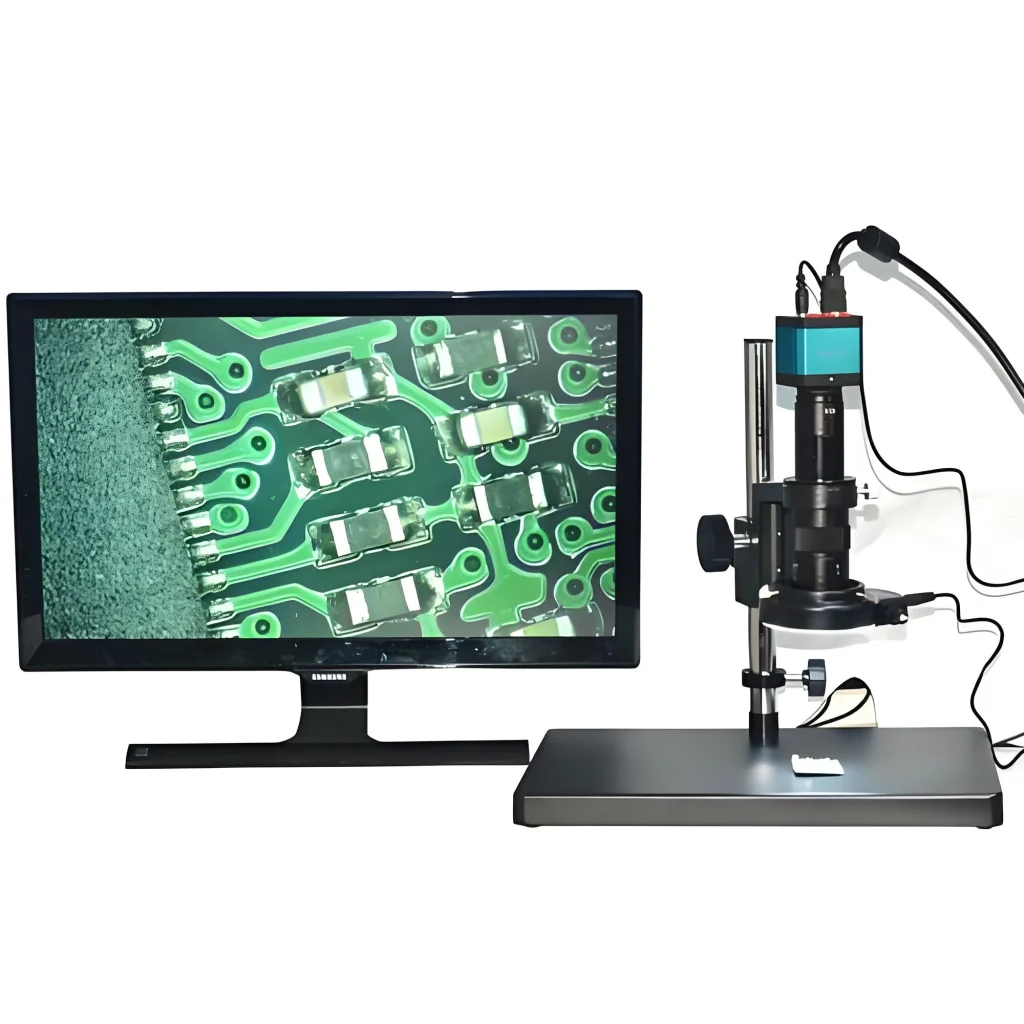
Visual Physical Inspection: First, observe the capacitor surface for bulges, leakage, burning discoloration, or mechanical cracks using a high-power microscope or with the naked eye to rule out obvious physical damage.
Safe Discharge and Static Defense: Completely disconnect the power supply and release residual charge. Use a low-power DC resistance test setting to quickly check for absolute short circuits in all power rails of the board.
High-Frequency ESR Precise Location: Using a low-voltage, high-frequency ESR tester, without triggering surrounding semiconductor PN junctions, perform ESR impedance screening on electrolytic capacitors and critical filter nodes to identify potentially degraded capacitors.
Dynamic electromagnetic and thermodynamic assistance: For hidden power rail short circuits or decoupling failures, combining oscilloscope ripple analysis and infrared thermal imaging hotspot tracking methods allows for pinpointing the culprit from both thermal and high-frequency noise perspectives.
By understanding the microscopic equivalent model of capacitors and mastering the propagation laws of electromagnetic signals in distributed networks, engineers can penetrate the fog of bypass effects in complex circuits, achieving high-efficiency, non-destructive, and accurate testing and diagnosis of circuit board capacitors.