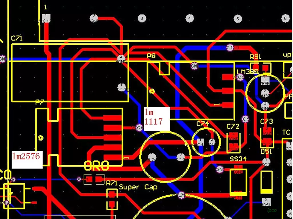
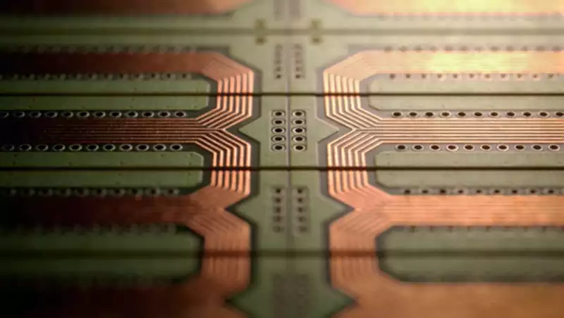
When routing differential wiring on 4 layer pcbs, inadvertent interlayer transitions can readily cause signal distortion and a sharp decline in product yield. Unlike single-layer or thick multilayer boards, the compact space and fixed interlayer dielectric in 4-layer boards make differential wiring transitions prone to impedance discontinuities and timing deviation issues. Mastering core techniques is essential to balance signal integrity with manufacturing feasibility.
Core Challenges in Differential Wiring Layer Transition for 4 layer PCBs
The essence of differential wiring lies in leveraging symmetrical transmission to counteract interference. The most prominent challenge during layer transitions in 4 layer PCBs is impedance discontinuity, which disrupts signal synchronisation and induces reflection losses.
The mainstream 4 layer stackup comprises two signal layers flanked by two power/ground planes. Interlayer transitions necessitate cross-plane routing, which can fragment signal return paths and exacerbate crosstalk—particularly pronounced at high frequencies.
Furthermore, suboptimal via design and mismatched trace lengths during interlayer transitions further degrade signal quality. This may render end devices inoperable and inflate PCB manufacturing costs.
Core Principles of 4 layer pcb Laminate Structures and Layer Transition
The foundation for differential wiring layer transitions in 4 layer pcb lies in defining the laminate structure and leveraging complete reference planes to minimise interference. This constitutes the core prerequisite for all transition techniques.
Two primary 4 layer stackups exist:
- Top layer (signal) – GND – Power – Bottom layer (signal)
- Top layer (signal) – Power – GND – Bottom layer (signal)
The former is preferred, as the GND plane provides a stable return path.
Regardless of stackup, differential wiring layer transitions must adhere to the principle:
Transition differential pairs within the same group to the same signal layer category,
avoiding segmentation across power/ground planes.
Prior to transitioning, verify the dielectric thickness and permittivity between layers. Calculate the target differential impedance (typically 100Ω ±10%) to ensure post-transition impedance deviation remains within acceptable limits.
Simultaneously, pre-plan transition locations to avoid high-density component areas. Reserve space for via placement, balancing differential wiring transitions with PCB manufacturability to minimise fabrication complexity.
Core Switching Techniques for Differential Wiring in 4 layer pcbs
1: Prioritise avoiding unnecessary layer-to-layer switching. Where differential wiring can be completed within the same signal layer, resolutely avoid cross-layer transitions to minimise signal interference and impedance variations at source.
If switching is unavoidable, prioritise direct ‘top layer → bottom layer’ transitions. Utilise GND/power planes as reference points to avoid multiple cross-layers, reduce via counts, and minimise signal loss.
2: Cross-plane transitions require ‘proximity return paths’. Add ground vias at transition points to shorten return paths, compensating for signal fragmentation caused by cross-plane transitions and suppressing crosstalk.
Ground vias must be positioned close to differential wiring transition vias, with spacing controlled within 2mm. Their quantity should match differential pair vias to ensure unobstructed return paths and enhance signal stability.
3: Via design must be symmetrical and consistent. Inter-layer differential wiring transition vias should be laid out in pairs, using 8mil/16mil aperture specifications to minimise impedance transition.
Via spacing must align with the trace spacing of differential wiring on the same layer. This prevents differential pair asymmetry caused by via misalignment, ensuring synchronous transmission of both signal lines and reducing timing differences.
4: Strictly control trace length matching after layer transitions. Differential pair length deviation before and after transitions must be ≤5mil. For excessive deviation, compensate using serpentine routing, ensuring symmetry.
Serpentine routing must be positioned near the transition origin to avoid excessive length increasing signal delay. Maintain trace spacing consistent with differential trace spacing to prevent introducing additional crosstalk.
5: Impedance compensation must accommodate layer-to-layer variations. Different signal layers may feature varying dielectric thicknesses and copper foil weights. Post-transition, fine-tune trace widths and spacings to maintain differential impedance at the 100Ω standard.
For instance, if the top layer trace width is 8mil, transitioning to the bottom layer may require adjustment to 7-9mil based on the bottom layer’s dielectric thickness. This compensates for impedance shifts caused by layer-to-layer differences, ensuring signal integrity.
Precautions for Differential Wiring Switching on 4 layer PCBs
1.Differential wiring must not cross power/ground plane partitioning areas. Partition lines disrupt return paths, significantly increase crosstalk, and may cause signal distortion.
If crossing partitions is unavoidable, add bridging vias at the partition point to establish temporary return paths. Ensure no fewer than two bridging vias are used to guarantee unimpeded return flow.
2.Avoid arbitrarily enlarging via apertures. Excessively large vias exacerbate impedance discontinuities while occupying excessive PCB space, compromising component placement and differential wiring layout.
Via fabrication must comply with PCB manufacturing specifications, with aperture tolerances controlled within ±0.5 mil. Insufficient via precision may cause differential pair asymmetry, adversely affecting transition performance.
3.Post-switching simulation verification is mandatory. Employ EDA tools to simulate signal transmission after differential wiring switching, identifying impedance discontinuities, crosstalk, and other issues.
Should simulations fail, prioritise adjustments to switching locations, via placement, or trace width/spacing over indiscriminate ground via additions. Balance signal performance with manufacturing costs.
4.Ensure process compatibility: The via spacing and trace width/spacing for differential wiring transitions must align with the PCB manufacturer’s processing capabilities. Avoid designs exceeding mass production feasibility to prevent yield degradation.
Interlayer switching in differential wiring for 4 layer pcbs constitutes a critical step in ensuring signal integrity and enhancing product yield. By thoroughly understanding the structural characteristics of 4 layer pcbs, adhering to sound switching principles, and applying effective switching techniques, engineers can significantly mitigate signal distortion and impedance discontinuities. Concurrently, paying close attention to all considerations during the switching process ensures design feasibility and manufacturing efficiency, laying a solid foundation for producing high-quality PCB products.