In today’s electronics manufacturing industry, rigid PCB (Printed Circuit Board) fabrication and PCBA (Printed Circuit Board Assembly) are two indispensable stages in the production of electronic products. A PCB serves only as the structural and electrical foundation of a circuit. It becomes a fully functional electronic assembly only after SMT component placement, soldering, assembly, and final integration into a PCBA. Furthermore, standardized interconnection technologies are required to establish reliable electrical connections between multiple circuit boards, external modules, and electronic components before the complete electronic system can operate properly.
PCBA manufacturing extends far beyond PCB fabrication, SMT assembly, and solder joint formation. It also includes standardized board-to-board, board-to-component, and board-to-module connection technologies that ensure reliable electrical transmission throughout the entire system. Since different connection methods vary considerably in terms of manufacturing cost, reliability, serviceability, and suitability for mass production, the electronics industry has developed three primary categories of interconnection technologies: direct soldered connections, connector-based connections, and specialized connection methods designed for unique manufacturing requirements.
Direct Soldered Connections
Direct soldering is the most traditional, widely adopted, and cost-effective method for establishing electrical connections between PCBs. Thanks to its low manufacturing cost, exceptional mechanical stability, and excellent resistance to electrical interference, it remains the preferred solution for simple electronic products and low-to-medium volume production.
By permanently joining conductors through molten solder, this method eliminates intermediate connectors and significantly reduces failures caused by loose contacts, oxidation, poor electrical contact, or intermittent signal transmission. As a result, long-term operational reliability is greatly improved, making this technology common across a broad range of consumer electronic products.
Depending on the application, direct soldering can generally be divided into PCB wire soldering and PCB power socket connections.
PCB Wire Soldering
PCB wire soldering is a connector-free interconnection method that directly joins copper wires or tinned cable assemblies to PCB pads and connection points. The wires are soldered directly to another PCB, an external component, or a power module to establish electrical continuity without requiring additional connectors.
This process is simple, economical, and highly adaptable, making it particularly suitable for products with few external wiring requirements, uncomplicated circuit structures, and no need for future disassembly or maintenance. Typical applications include speaker wiring inside traditional radios, battery pack connections, and internal wiring for compact lighting products.
When multiple PCBs need to be interconnected, ribbon cables are generally preferred over individual wires. Multi-core ribbon cables provide organized routing, minimize signal interference caused by tangled wiring, accurately align with board connection points, and significantly reduce wiring errors. Their superior reliability and neat cable management make them the preferred solution for simple multi-board electronic systems.
PCB Power Socket Connections
As electronic equipment becomes more sophisticated and increasingly requires mass production, maintenance, and future upgrades, direct wire soldering gradually reveals its limitations. PCB power socket connections were therefore developed to provide a more practical and serviceable alternative.
This method adopts a modular plug-and-socket architecture. During PCB design, dedicated board-edge connectors are incorporated, with the connector dimensions, pin count, contact spacing, mounting holes, and mechanical structure precisely matched to standardized sockets. This ensures accurate alignment, secure engagement, and reliable electrical performance.
Compared with manual wiring, integrated board-mounted connectors provide significantly greater assembly consistency and are ideally suited to automated production environments. The modular design also enables rapid installation and removal of circuit boards. During maintenance, technicians can simply unplug and replace an individual PCB without dismantling the entire device, greatly reducing both manufacturing costs and long-term maintenance expenses. Consequently, this technology is widely used in industrial automation equipment, precision instruments, and industrial control systems.
Connector-Based Connections
As electronic products continue to achieve higher levels of integration and shorter product life cycles, repairability, modular replacement, and product upgrades have become increasingly important. Permanent soldered connections are no longer suitable for many advanced electronic systems.
Connector-based interconnection technology has therefore become the dominant solution for complex electronic products because it supports repeated insertion and removal, rapid assembly, modular system design, and efficient large-scale manufacturing. Instead of permanent solder joints, standardized electrical connectors establish reliable board-to-board connections while allowing fast installation, replacement, and maintenance.
The two most common forms are standard pin header connections and wire jumper connections.
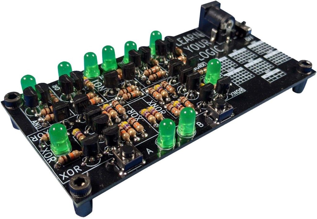
Standard Pin Header Connections
Standard pin header connections represent the most widely used board-to-board interconnection technology in industrial electronics. Standard pin headers, female sockets, and board-to-board connectors provide reliable electrical connections between two or more PCBs.
During assembly, the male pin header is soldered onto one PCB while the corresponding female connector is soldered onto the mating board. Electrical connection is established simply by inserting the two connectors together.
This method offers exceptional flexibility in mechanical design, allowing PCBs to be connected in parallel, vertically, or at offset angles according to the internal structure of the product. Standardized connectors are inexpensive, highly compatible, easy to assemble, and well suited to automated production lines. They provide excellent connection accuracy while significantly improving manufacturing efficiency and are extensively used in consumer electronics, smart home products, automotive electronic modules, and numerous mass-produced electronic devices.
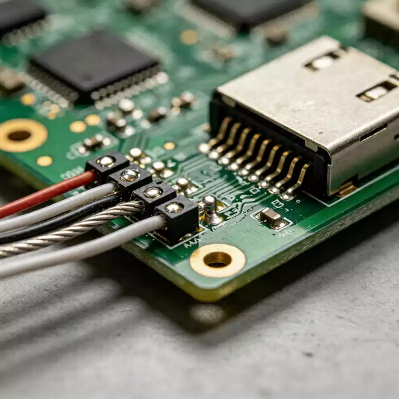
Wire Jumper Connections
Wire jumper connections provide a simple method for connecting a PCB to external electronic modules, independent functional units, or peripheral components. Dedicated connection pads on the PCB are linked to external circuits through specialized wires, allowing flexible electrical routing between internal and external circuits.
Compared with conventional board-to-board connectors, wire jumper connections offer greater routing flexibility. However, careful cable management is essential. Mechanical vibration, cable movement, repeated bending, and electromagnetic interference caused by poorly organized wiring may all affect long-term reliability. Proper cable fixation, harness organization, and electromagnetic shielding are therefore necessary to prevent wire damage, signal interference, poor contact, or open circuits.
Specialized PCB Connection Technologies
In addition to conventional soldering and connector-based assembly, certain manufacturing scenarios—including high-volume PCB production, flexible circuit assembly, and integrated multi-board modules—require specialized connection technologies that conventional methods cannot adequately support. These specialized processes have been developed specifically to address the unique requirements of panelized manufacturing, flexible electronics, and advanced multi-board integration.
V-Scoring and Copper Foil Bridges
V-scoring and copper foil bridge technology are complementary processes widely used in panelized PCB manufacturing.
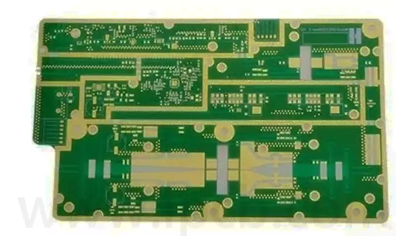
To improve production efficiency, reduce manufacturing costs, and ensure dimensional consistency, manufacturers typically fabricate multiple identical PCBs on a single large production panel.
V-scoring creates precisely controlled V-shaped grooves along the separation lines while leaving a thin layer of substrate connecting adjacent boards. This allows the complete panel to proceed through SMT assembly, soldering, plating, and inspection as one unit before the individual boards are easily separated with minimal force. The resulting edges are clean and do not damage the circuit traces.
Copper foil bridges further strengthen the mechanical integrity of the production panel by temporarily connecting adjacent boards with narrow copper sections. Together, V-scoring and copper foil bridges greatly improve manufacturing efficiency, panel stability, and production yield.
Spring and Spring Contact Connections
Spring-loaded contacts and spring connectors provide flexible electrical connections specifically designed for flexible printed circuits (FPCs) and irregularly shaped PCBs. They are widely used in wearable electronics, foldable devices, and miniature precision products.
Unlike rigid soldered or plug-in connections, these systems rely on spring contacts, pogo pins, or elastic metal contacts to generate continuous mechanical pressure between two circuit boards, thereby maintaining reliable electrical contact.
The elastic structure effectively accommodates bending, vibration, and slight mechanical deformation while reducing failures associated with rigid connections. Because no soldering or permanent fastening is required, assembly and maintenance are greatly simplified, and service life is extended. This technology is commonly found in FPC interconnections, wearable devices, miniature sensors, and foldable electronic products.
Panelized Integrated Connections
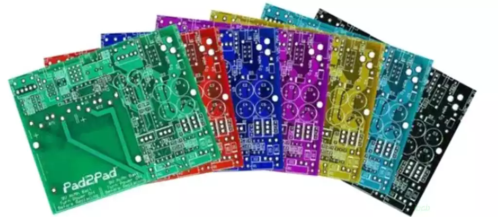
Panelized integration, also referred to as PCB panelization, is one of the most important manufacturing technologies for high-volume PCB production and module assembly.
Multiple PCB designs of varying sizes and functions are arranged together on a single manufacturing panel, allowing all SMT assembly, soldering, inspection, and testing operations to be completed simultaneously. This approach maximizes material utilization, minimizes waste, standardizes manufacturing processes, and significantly increases production efficiency.
After all manufacturing processes have been completed, the individual PCBs are separated from the panel using mechanical routing, V-scoring, or laser depaneling techniques. The result is a collection of fully assembled individual PCB modules ready for final product integration.
Panelized manufacturing perfectly matches the requirements of standardized, high-volume electronics production and has become one of the industry’s most effective methods for reducing manufacturing costs while improving production efficiency.
Each PCB and PCBA interconnection technology offers distinct technical advantages and is optimized for specific application requirements. In practical electronics manufacturing, engineers select the most appropriate combination of connection methods based on product architecture, production volume, operating environment, and maintenance requirements. By balancing electrical reliability, signal integrity, manufacturing efficiency, production cost, and long-term serviceability, manufacturers can achieve the optimal overall performance and lifecycle value for modern electronic products.