Single point grounding means that there is only one physical point in the entire circuit system that is defined as the ground reference point, and all other points that need to be grounded are connected directly to this point. In low-frequency circuits, there is not much influence between wiring and components. Usually circuits with frequencies less than 1MHz are grounded at one point.
The single-point grounding method is problematic if the system operates at such a high frequency that the operating wave length is comparable to the length of the system grounding lead.
When the length of the local line is close to 1/4 wavelength, it is like a terminal short-circuit transmission line, the ground current, voltage is standing wave distribution, the ground becomes a radiating antenna, and can not play the role of “ground”. In order to reduce the ground impedance, to avoid radiation, the length of the ground should be less than 1/20 wavelength. In the treatment of the power supply circuit, you can generally consider a single point of grounding.
(1) Series single-point grounding
For series single-point grounding, if the power of the modified circuit is very large, it will generate a large circuit return current, which will produce a voltage drop in the finite impedance, resulting in a difference in the voltage reference between the circuit and the reference ground that may not allow the system to work as expected.
If the system has multiple circuits of different power levels, it is not possible to use series single point grounding because the high power circuits generate a large return current to ground that will affect the low power devices and circuits. If this grounding method must be used, then sensitive circuits must be set directly at the power input location and principle low power devices and circuits as much as possible. If the grounding level of each circuit does not differ significantly, this method can be used.
(2) parallel single-point grounding
Parallel single-point grounding method, each circuit unit alone with a land line linked to the same location, the advantage is that the location of the circuit is only with the circuit’s ground current and low impedance, not affected by other circuits. At low frequencies, it can effectively avoid the low resistance between each unit circuit anti-interference, but there are many disadvantages. The main performance:
Each circuit Fern don’t use independent ground wire grounding, need more than one ground wire, will inevitably increase the length of the ground wire, thus increasing the low impedance, the structure of the complexity of the use of trouble;
This grounding method will cause mutual coupling between the ground, and with the increase in frequency, ground impedance, ground inductance, ground capacitance will increase, this grounding method is not applicable to high-frequency circuits.
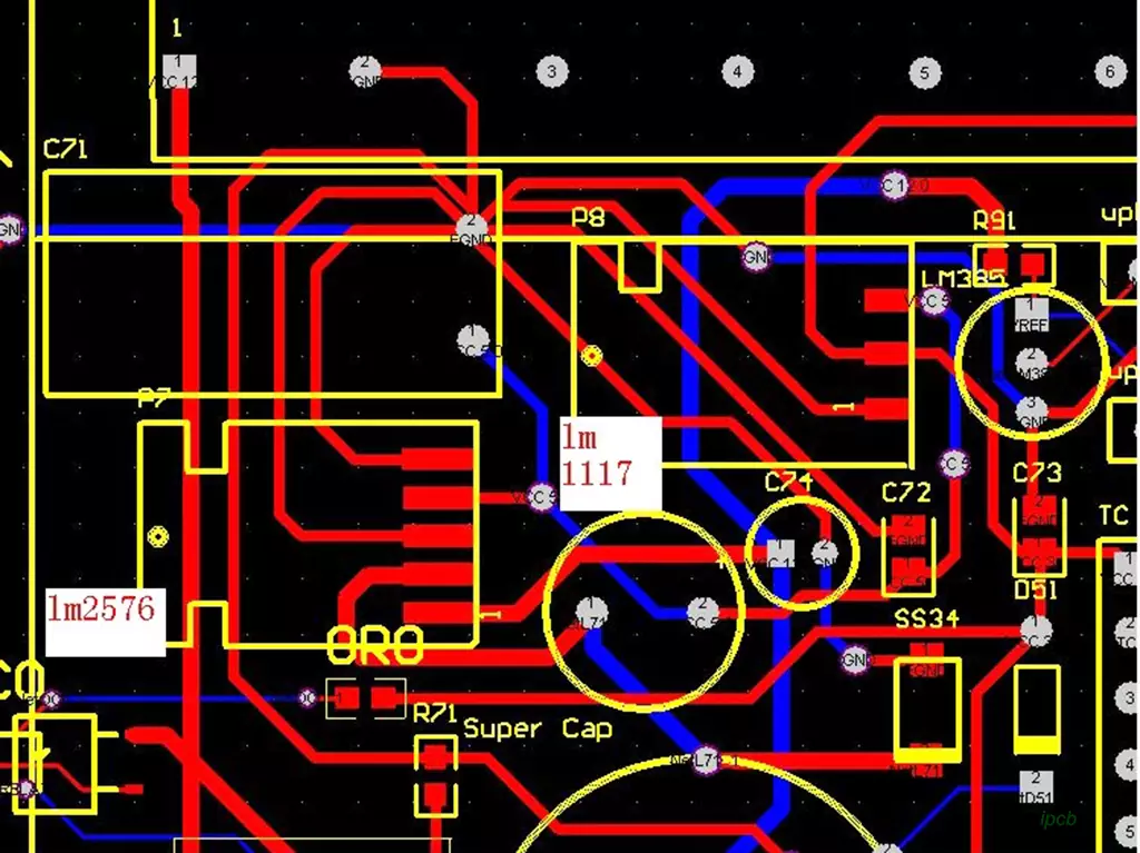
Multi-point grounding
Multi-point grounding refers to the signal and power lines are connected to different grounding points. This method can effectively reduce the grounding resistance, reduce electromagnetic interference and signal reflection and other issues. However, multi-point grounding requires precise control in circuit board design and manufacturing to ensure that the potential of each grounding point is the same.
Hybrid Grounding
Hybrid grounding is a combination of single-point grounding and multi-point grounding of the grounding method, generally on the basis of single-point grounding through some inductive or capacitive multi-point grounding. Because inductance, capacitance at different frequencies have different impedances and thus constitute a different grounding structure. Mixed grounding is mostly applicable to circuits operating at mixed frequencies.
Virtual Ground
A virtual ground is a ground point that is connected to another signal line instead of an actual ground. Virtual grounding can eliminate ground loops and reduce EMI in circuit board design. However, a virtual ground requires sophisticated control and testing to ensure that it works properly.
In a circuit, grounding can serve the following purposes:
Protect people and equipment in the circuit
With grounding, the current in a circuit can flow back to ground, thus protecting people and equipment from hazards such as electric shock.
Suppressing electromagnetic interference
In circuit boards, many signal and power lines require grounding. These grounding points eliminate electromagnetic interference between signal and power lines, improving the reliability and stability of the circuit.
Stabilizes Voltage and Current
In circuit boards, grounding also stabilizes the voltage and current to a certain range.
The choice of PCB grounding strategy should be based on the operating frequency of the specific circuit, power level, electromagnetic interference and other factors for comprehensive consideration. Through the reasonable selection and application of grounding technology, it can ensure the stable operation of the circuit and improve the reliability and stability of the system.
