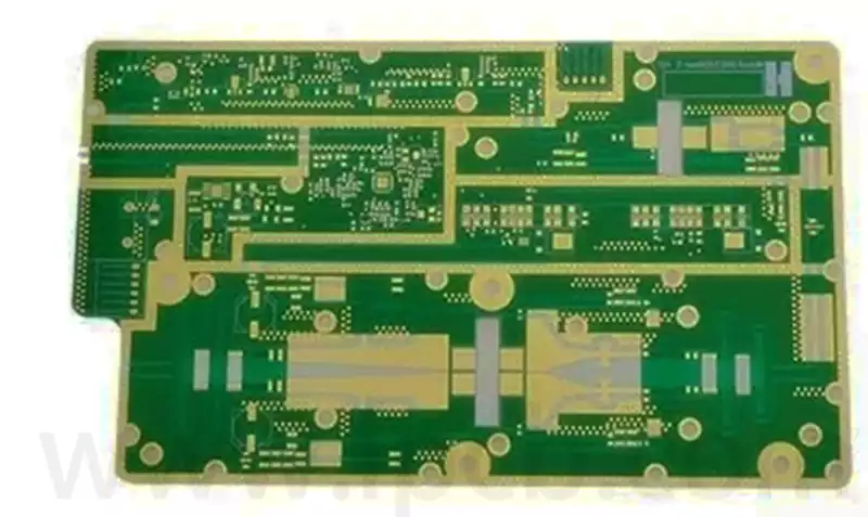
In our PCB development work, we often face the same challenge. Engineers want higher frequency performance, but many existing boards still rely on standard FR-4 materials. On our production floor, we frequently see design teams struggle when signals begin to degrade at higher frequencies. The problem becomes clear during testing: signal loss rises, stability drops, and performance does not meet expectations. This creates pressure for designers and manufacturers alike.
Standard FR-4 materials face clear limitations in high-frequency applications because their dielectric loss and signal dispersion increase as frequency rises. However, engineers are exploring improved FR-4 formulations, hybrid materials, and alternative laminates to extend performance while controlling cost.
To understand the future of FR-4, we need to look deeper. First we must understand why the limitations appear. Then we can explore alternative materials and improvement strategies that push FR-4 closer to high-frequency demands.
The Root Cause of High-Frequency Limitations in Standard FR-4 Materials?
During many board validation projects in our engineering lab, we often observe the same pattern. A PCB works well at low frequencies, but once the signal speed increases, problems appear. Designers feel confused because FR-4 has been reliable for decades. However, when we examine the material properties more closely, the reasons become clearer.
Standard FR-4 struggles in high-frequency environments because its dielectric constant varies with frequency and its dielectric loss is relatively high. These characteristics cause signal attenuation, impedance instability, and increased noise, making FR-4 less suitable for RF and microwave circuits.**
Dielectric Loss Becomes a Major Problem
FR-4 uses epoxy resin reinforced with glass fiber. This structure works well for mechanical strength and cost efficiency. However, epoxy resin introduces higher dielectric loss when frequency increases.
At high frequencies, signal energy converts into heat inside the dielectric material. This process weakens the signal and reduces transmission quality.Even small losses can create serious problems in RF systems.
| Property | Typical FR-4 Value | Impact at High Frequency |
| Dielectric Constant (Dk) | 4.2–4.8 | Causes impedance variation |
| Dissipation Factor (Df) | 0.015–0.025 | Leads to signal loss |
| Thermal Stability | Moderate | Affects long-term reliability |
Signal Integrity Challenges
Another issue we often observe during testing is signal distortion. When signals travel through a PCB trace, the dielectric constant affects propagation speed.
FR-4 materials do not maintain a perfectly stable dielectric constant across frequency ranges. This variation leads to phase errors and timing issues.
| Frequency Range | Performance of Standard FR-4 |
| Below 1 GHz | Stable and reliable |
| 1–5 GHz | Moderate signal loss |
| Above 5 GHz | Noticeable attenuation |
For modern systems like radar, 5G communication, and satellite electronics, these limitations become critical.
Moisture Absorption Effects
FR-4 material can absorb small amounts of moisture from the environment. This may seem minor, but moisture changes dielectric properties.
In our testing environment, we sometimes see performance variations after humidity exposure. This effect becomes more serious for high-frequency signals.
As frequency rises, every small material change affects performance. That is why designers begin searching for better solutions.
Alternative Options to Standard FR-4 Materials for High-Frequency Applications?
In recent years, many engineers who work with us on advanced electronic systems have started exploring alternative laminates. Standard FR-4 is still widely used, but certain applications demand materials with lower dielectric loss and higher stability.
Several materials perform better than standard FR-4 in high-frequency circuits, including PTFE-based laminates, hydrocarbon ceramic substrates, and modified epoxy composites. These materials offer lower dielectric loss, more stable dielectric constants, and improved signal integrity for RF and microwave systems.
PTFE-Based Materials
Polytetrafluoroethylene (PTFE) laminates are widely used in RF systems.These materials provide very low dielectric loss. That means signals can travel longer distances without degradation.
| Material | Dielectric Constant | Loss Factor | Typical Applications |
| PTFE | 2.1 | Very Low | Radar systems |
| Rogers 4350B | 3.48 | Low | RF circuits |
| Standard FR-4 | ~4.5 | Higher | General electronics |
However, PTFE also brings challenges. It is more expensive and more difficult to process during PCB manufacturing.
Hydrocarbon Ceramic Materials
Hydrocarbon ceramic laminates represent another option. These materials combine organic polymers with ceramic fillers.
The advantage is balanced performance. Engineers gain lower dielectric loss without the full cost of PTFE.These materials also offer better thermal stability.
Modified Epoxy Laminates
Another interesting development we see in PCB material supply chains is modified epoxy systems. These materials are designed to behave similarly to FR-4 but with improved electrical properties.
They keep the manufacturing familiarity of FR-4 while improving signal performance.
| Feature | Standard FR-4 | Modified High-Speed Epoxy |
| Cost | Low | Medium |
| Signal Loss | Moderate | Lower |
| Manufacturing Difficulty | Easy | Easy |
Because of this balance, many high-speed digital designs choose modified FR-4 material instead of switching to expensive RF materials.
Strategies for Enhancing Standard FR-4 Materials for High-Frequency Compatibility?
While many alternatives exist, cost still matters. In many projects we support, engineers want to keep FR-4 but improve its performance. This goal drives research into enhanced FR-4 formulations and smarter PCB design strategies.
Standard FR-4 materials can be improved for higher-frequency use by modifying resin systems, optimizing glass weave structures, and applying better PCB design techniques such as impedance control, shorter signal paths, and careful stack-up engineering.
Improved Resin Formulations
Material scientists are developing new epoxy blends that reduce dielectric loss.These resins maintain mechanical strength but reduce energy dissipation. As a result, signal transmission improves.
Glass Weave Optimization
The glass fiber structure inside FR-4 can create uneven dielectric properties.Modern laminates use tighter and more uniform weave patterns.This improvement reduces signal skew in high-speed digital systems.
| Glass Style | Performance Impact |
| Standard weave | Higher skew risk |
| pread glass | Better signal uniformity |
| Flat glass structure | Improved impedance stability |
PCB Design Techniques
Material improvements alone are not enough. Designers must also optimize PCB layout.Several strategies can extend FR-4 performance.When these techniques are combined, FR-4 can support higher frequencies than many engineers expect.
| Design Strategy | Benefit |
| Controlled impedance routing | Reduces reflections |
| Shorter trace lengths | Minimizes loss |
| Differential signaling | Improves noise immunity |
| Careful stack-up design | Stabilizes signal paths |
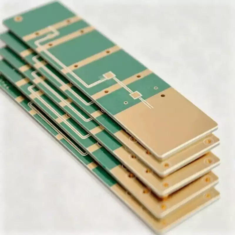
Hybrid Stack-Up Structures
Another approach we sometimes see in advanced designs is hybrid PCB stack-ups.In this design, only the RF layers use high-frequency materials. Other layers remain FR-4.This strategy balances performance and cost.For example, a 6-layer PCB might use RF laminate on two layers and FR-4 on the rest.This method reduces material cost while maintaining RF performance.
FR-4 material remains one of the most widely used PCB materials in the electronics industry. However, its dielectric loss and signal instability create challenges in high-frequency applications. Engineers now explore several paths forward, including alternative laminates, modified epoxy systems, and improved PCB design strategies. In many cases, hybrid solutions offer the best balance between performance and cost. By understanding the limitations and exploring new material technologies, designers can continue extending the useful range of FR-4 in modern high-frequency electronics.