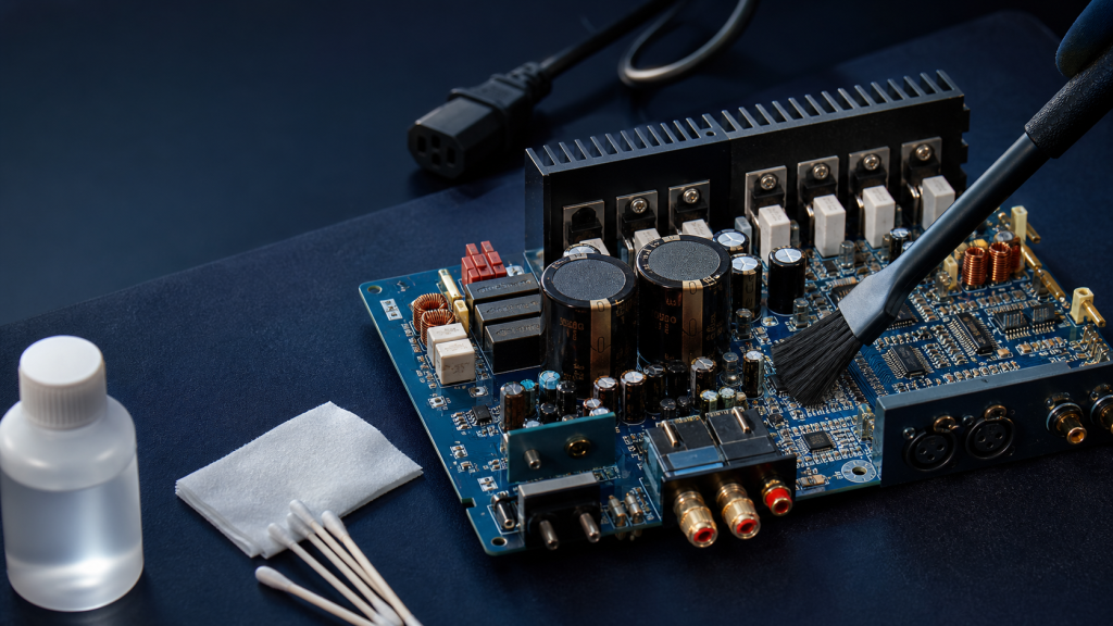
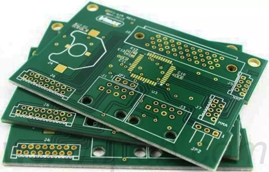
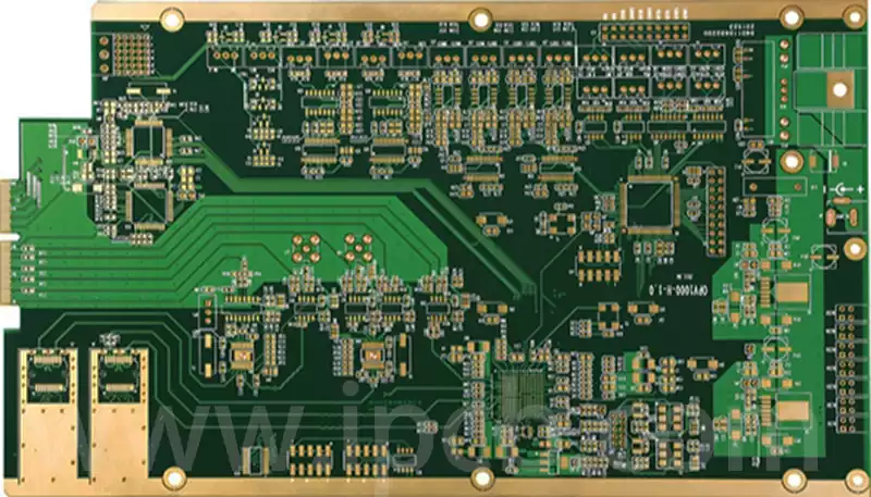
A prototype printed circuit gives engineers a physical version of a PCB design that can be assembled, powered, measured, and evaluated before the product moves into regular production. A schematic and PCB layout can appear correct during design review, but the physical board may reveal problems involving component placement, signal behavior, thermal performance, mechanical fit, assembly, or manufacturing tolerances. Building a prototype creates an opportunity to identify these issues while the design can still be changed without affecting a larger production run.
Turning a PCB Design Into Something Engineers Can Test
The value of a prototype printed circuit begins before fabrication. Once the schematic and layout have been developed, engineers need to make sure that the design data is complete enough for manufacturing and assembly. This normally includes the PCB layout, fabrication outputs, board specifications, component information, and assembly documentation where required.
At this stage, the purpose is not simply to check whether the board can be manufactured. The prototype should be connected to specific engineering questions. A simple control board may need to confirm that its inputs, outputs, and power circuits operate correctly. A high-speed board may require measurements of signal behavior or impedance-related performance. A compact electronic product may need to confirm that connectors, mounting holes, switches, displays, and other mechanical features fit the intended enclosure.
The PCB stack-up and material selection also become important when the prototype is expected to represent the eventual product. Layer count, dielectric structure, copper thickness, controlled impedance requirements, thermal conditions, and mechanical requirements can all affect the physical behavior of the finished board. IPC provides separate design standards for areas such as rigid boards, flexible boards, HDI, and high-speed circuitry, reflecting the different requirements that can arise from the intended application.
A design rule check and manufacturing review should therefore be completed before the files are released. Issues such as insufficient spacing, unsuitable hole sizes, difficult-to-manufacture features, component clearance problems, or inaccessible test locations are easier to correct in the design files than after fabrication.
What the First Prototype Can Reveal
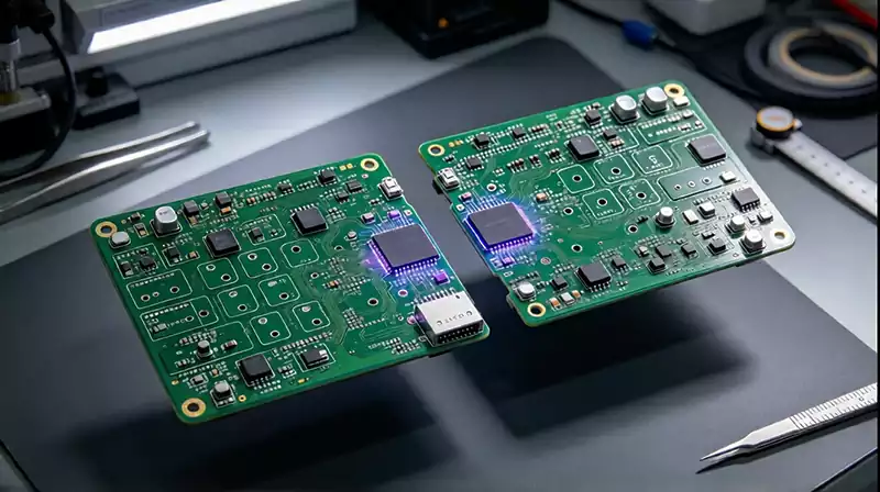
The first physical printed circuit board often answers questions that cannot be fully resolved from CAD data alone. Electrical testing can show whether power rails reach their expected values, whether circuit blocks communicate correctly, and whether measured signals correspond with the design assumptions. For more complex systems, engineers may also examine signal integrity, thermal behavior, current consumption, startup behavior, or interaction between different circuit sections.
The physical arrangement of components is another important part of prototype evaluation. A connector may be electrically correct but difficult to access after the board is installed in an enclosure. A component may meet the schematic requirements but interfere with a mechanical structure. A heat-generating device may require a larger copper area or a different thermal path than originally planned.
Assembly can reveal another group of problems. Fine-pitch components, closely spaced parts, connectors, test points, and unusual component orientations may create manufacturing or inspection difficulties. The prototype provides an opportunity to evaluate these issues before the design becomes difficult to change.
Testing should follow the actual purpose of the board. If the prototype is intended to validate a power circuit, measurements should focus on voltage, current, load behavior, temperature, and other relevant operating conditions. If it is a communication board, interface operation and data transmission may be more important. A useful prototype test is therefore based on defined requirements rather than a generic pass-or-fail inspection.
Making the Prototype Useful for the Next Revision
A prototype should generate information that can be fed back into the next design revision. Engineers can record electrical measurements, mechanical observations, assembly problems, thermal results, and other findings during evaluation. These results can then be compared with the original design requirements.
This feedback loop is particularly important when the first board does not perform as expected. A failed prototype does not necessarily mean that the overall product concept is unsuitable. The problem may be related to component selection, routing, grounding, power distribution, thermal design, firmware interaction, or another part of the implementation. Separating these issues helps engineers determine what needs to change before another prototype is built.
Design for manufacturability should remain part of this process. IPC describes DFM as an important part of product development and provides design profiles covering different performance classes and producibility levels. This approach recognizes that PCB designs need to account for manufacturing requirements before production rather than treating manufacturability as a problem to solve afterward.
The transition from one prototype revision to the next should also be controlled carefully. Changes to the schematic, PCB layout, BOM, fabrication files, and assembly documentation need to remain synchronized. Otherwise, an engineering team can end up testing a board that does not correspond to the intended revision. Clear revision control becomes increasingly important as more prototypes are produced.
Moving From Prototype to Production
A successful prototype is not automatically a production-ready PCB. Before volume manufacturing, the design may need another review to confirm that remaining engineering changes have been incorporated and that the manufacturing process can reproduce the required board consistently.
At this stage, engineers may revisit the PCB stack-up, materials, trace and spacing requirements, via structures, component footprints, panelization, assembly process, test access, and other manufacturing details. Features that were acceptable for a small prototype run may need optimization when production quantities increase. The goal is to maintain the required electrical and mechanical performance while making the board practical to manufacture repeatedly.
The prototype can also serve as a reference for production testing. Test points, functional checks, inspection requirements, and acceptance limits identified during development can be incorporated into the production test strategy. This creates a clearer connection between engineering validation and manufacturing quality control.
For complex boards, the transition can involve several prototype revisions rather than a single build. High-density, high-speed, RF, thermal, and mechanically constrained designs may require additional iterations because several engineering variables interact with one another. The prototype process therefore works best as a controlled development cycle rather than as a one-time manufacturing order.
A well-planned prototype printed circuit gives engineers physical evidence about how a PCB behaves outside the design environment. By connecting design verification, manufacturing review, assembly, testing, and revision control, the prototype stage can expose problems early and provide practical information for the next version of the board. This makes prototype printed circuit development an important bridge between PCB design and reliable production.