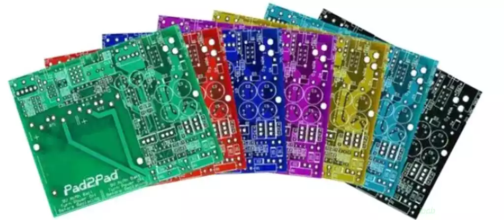
A control pcb determines how an electronic system responds to changing conditions. It receives information from sensors, switches, communication interfaces, or other circuits, processes that information according to programmed logic, and sends commands to the devices responsible for carrying out an action. The challenge is not simply to make these signals pass between components. A reliable control pcb board must ensure that inputs remain accurate, decisions are executed at the right time, and unexpected electrical conditions do not cause the system to behave unpredictably.
A Control PCB Must Connect Decisions to Physical Results
The operation of a control system depends on the relationship between its inputs and outputs. A temperature controller, for example, may receive a sensor reading, compare it with a target value, and activate a heater or cooling device. A motor controller follows a different sequence, using information such as speed, position, or current to determine the required drive signals. Although their functions differ, both systems depend on a clear path from signal acquisition to control action.
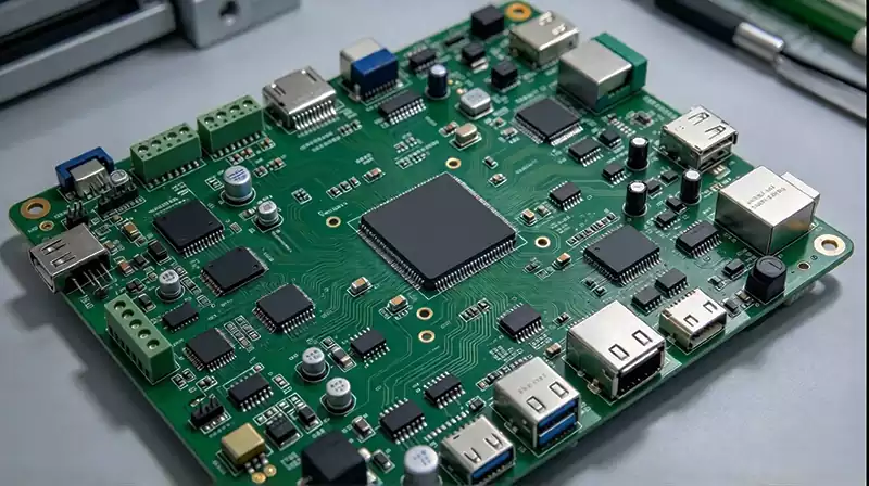
A typical control PCB may contain a microcontroller or processor, input-conditioning circuits, memory, communication interfaces, power regulation, and output drivers. These sections do not operate independently. The processor needs stable supply voltage and valid input signals, while the output stage must translate low-power control signals into electrical conditions suitable for the connected load. Feedback may then return information about the system’s actual state, allowing the controller to adjust its next action.
This relationship affects the entire design. If a sensor signal is distorted by electrical noise, the processor may make an incorrect decision even when the firmware works as intended. If an output driver cannot handle the load’s startup current, the commanded action may not occur reliably. Designing a control pcb therefore requires attention to the complete signal path rather than treating each circuit block as an isolated function.
Electrical Disturbances Can Change Control Behavior
Control electronics often operate alongside devices that generate electrical noise, including motors, relays, switching regulators, solenoids, and high-current power stages. Rapid switching can introduce voltage transients, electromagnetic interference, and ground disturbances. These effects may appear as unstable sensor readings, unexpected resets, communication errors, or incorrect switching behavior.
PCB layout plays an important role in limiting these problems. Sensitive analogue inputs should be considered in relation to nearby switching nodes, high-current paths, and clock signals. Return-current paths need to be predictable, and decoupling capacitors should be positioned close to the power pins they support. Where a design combines logic circuits with substantial switching currents, the layout must prevent noisy current loops from unnecessarily disturbing sensitive signals.
Grounding requires particular care. Separating analogue and digital functions can help organize the layout, but creating arbitrary ground splits may interrupt return-current paths and make interference worse. The appropriate arrangement depends on the circuit architecture, signal frequencies, current paths, and connections between functional sections. Similarly, isolation may be necessary where circuits operate at different voltage levels or where electrical safety requirements demand a defined barrier.
A reliable control pcb is designed around the disturbances it is expected to encounter, not just the conditions measured on an unloaded bench. Testing should include relevant switching events, load changes, startup conditions, and communication activity so that intermittent faults can be identified before deployment.
Power and Protection Determine How the Control PCB Handles Faults
The power supply affects more than whether a controller can turn on. Its voltage stability influences processor operation, sensor accuracy, communication reliability, and the behavior of output drivers. A control pcb board may require several supply rails for digital logic, analogue circuitry, communication interfaces, and external loads. Each rail must meet the voltage, current, ripple, and transient requirements of the circuits it serves.
Load switching creates additional demands. When a motor starts or a relay changes state, the resulting current changes can disturb a shared supply or ground network. Appropriate voltage regulation, local decoupling, transient suppression, and power-path design help reduce the risk. High-current loads may also require dedicated driver circuits or separate power sections, depending on the system’s requirements.
Protection must be matched to credible fault conditions. Depending on the application, a control board may need overcurrent protection, reverse-polarity protection, overvoltage handling, thermal monitoring, watchdog supervision, or defined behavior when a sensor signal becomes invalid. These measures serve different purposes: electrical protection limits damage to hardware, while control logic can place the system in an appropriate state when operating conditions fall outside acceptable limits.
The response to a fault should be defined during design rather than left to chance. For example, a controller may need to disable an output when feedback is lost, report a fault through a communication interface, or require a deliberate reset before restarting. The correct response depends on the equipment and its risk profile. A control pcb should support these decisions through suitable hardware, firmware interfaces, and testable fault-handling behavior.
Verification Should Reproduce Real Operating Conditions
A control pcb that powers up successfully has passed only an initial check. Verification should establish whether the control system performs correctly across its expected operating range. This includes checking supply rails, input thresholds, output behavior, communication interfaces, timing, and the response to representative load conditions. Where feedback control is used, engineers should also verify that sensor readings and actuator responses remain consistent during transitions rather than only under steady-state conditions.
Testing becomes more effective when the PCB design provides suitable access to important signals. Test points, programming interfaces, diagnostic connections, and accessible measurement locations can simplify troubleshooting during prototype development and production. For more complex boards, automated electrical tests may be combined with functional tests that exercise the intended control sequence.
Environmental and endurance testing should reflect the product’s intended use. Temperature changes, vibration, electrical disturbances, repeated switching, and extended operation may expose problems that are not visible during a short laboratory test. The required tests depend on the application, applicable standards, and the consequences of a failure.
Production consistency matters as much as prototype performance. Component substitutions, assembly variation, solder-joint defects, and changes in manufacturing processes can affect the finished control pcb board. Reviewing the bill of materials, confirming component orientation, inspecting critical solder joints, and applying repeatable test procedures help maintain consistent results across production batches.
Ultimately, a control pcb must do more than execute commands. It must acquire trustworthy information, make decisions reliably, deliver the intended outputs, and respond appropriately when conditions change. When the electrical design, control logic, protection strategy, and verification process are developed together, the board becomes a dependable part of the complete electronic system.