A pcb module is more than a small circuit board with electronic components. It is a functional unit designed to handle a defined task within a larger electronic system, such as power conversion, wireless communication, signal conditioning, sensing, or control. Its value depends not only on the circuit itself but also on how reliably it connects to the host system. A well-designed module establishes clear electrical and mechanical boundaries, making integration easier while helping engineers manage performance, testing, and future maintenance.
What Makes a PCB Module Different From a Bare PCB or PCBA
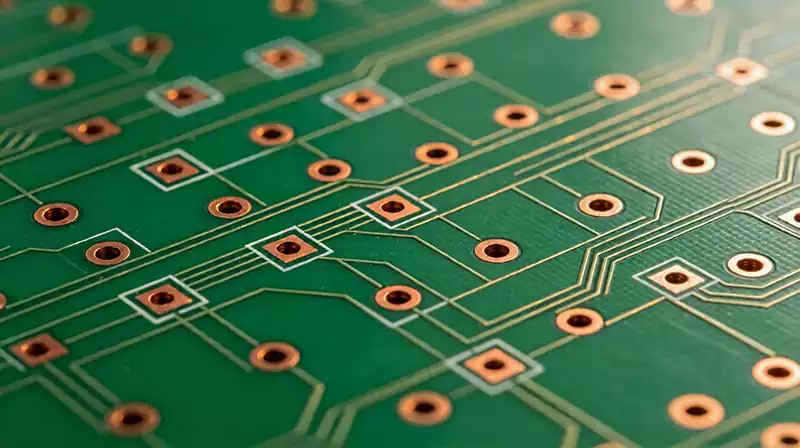
A bare printed circuit board provides the substrate, copper traces, pads, and vias needed to support and interconnect electronic components. Once components are mounted and soldered onto the board, the assembly becomes a PCBA. A pcb module, however, is defined primarily by its intended function and integration boundary.
For example, a populated board containing a voltage regulator, filtering components, and input and output connectors may serve as a power module. A communication module may combine a radio IC, supporting circuitry, an antenna interface, and a defined communication connection. Depending on the application, a module can consist of one assembled PCB, several interconnected boards, or a board integrated into a shielded or enclosed structure.
These terms can overlap in practice. A PCBA may serve as a module when it provides a sufficiently defined function and interface, but not every assembled circuit board is a complete module. The distinction matters because module development must account for the way the unit will be powered, controlled, mounted, tested, and maintained within the finished product.
Interface Design Determines Integration Success
The most important design boundary of a pcb module is the interface between the module and the host system. Even when the internal circuit operates correctly, mismatched voltage levels, insufficient current capacity, incompatible connectors, or unclear signal definitions can prevent reliable system operation.
Electrical interfaces should specify supply voltage ranges, peak and continuous current, signal levels, communication protocols, grounding requirements, and protection against expected electrical disturbances. High-speed digital or RF modules may also require controlled impedance, suitable return paths, and careful connector transitions. For power modules, voltage drop, switching noise, transient response, and current-return paths can be more important than simply fitting the circuit into a small footprint.
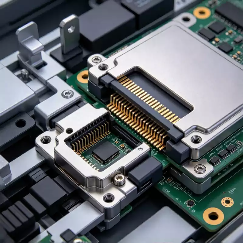
Mechanical integration deserves equal attention. The module outline, mounting points, connector orientation, component height, and clearance from surrounding structures must match the host design. Where a connector carries both mechanical stress and electrical current, its footprint and solder-joint design need to account for repeated insertion, vibration, or movement.
Defining these requirements early helps prevent a common integration problem: a module that works on a development bench but becomes unstable after installation in the final product.
Thermal Behavior and Signal Quality Must Be Designed Together
A compact pcb module can concentrate heat in a small area, particularly when it contains power converters, processors, RF amplifiers, or other components with significant power dissipation. Component placement, copper distribution, thermal vias, substrate selection, and the available heat-transfer path all influence operating temperature. Thermal design should reflect the actual enclosure and airflow conditions rather than assuming that the module will operate in open air.
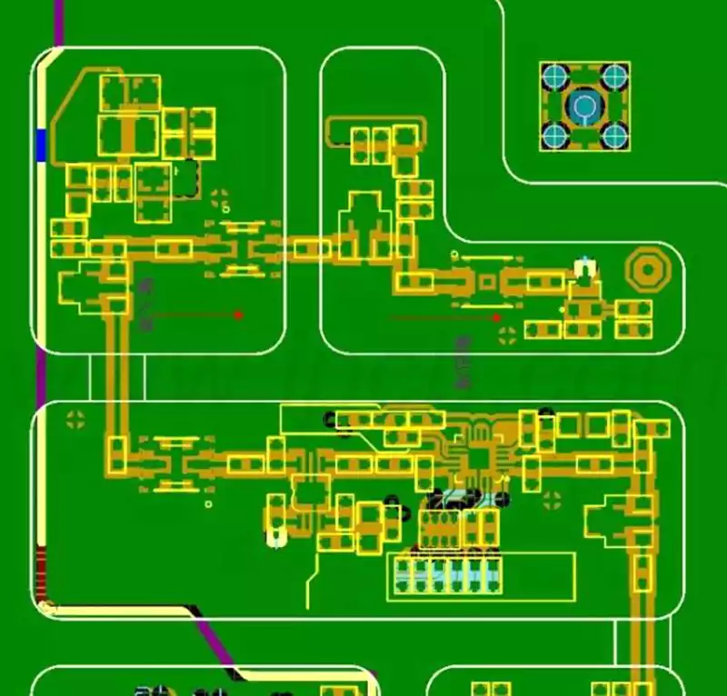
Signal quality also depends on the relationship between the module and its surrounding circuitry. Switching power stages can introduce noise into sensitive analog or RF sections, while poorly controlled return paths can increase electromagnetic interference. Separating noisy and sensitive circuit functions, placing decoupling capacitors near their intended loads, and maintaining appropriate reference planes can reduce these risks.
Shielding may be necessary when emissions or susceptibility requirements demand it, but a metal cover alone does not guarantee effective electromagnetic compatibility. Ground connections, seam design, connector openings, and the path of high-frequency currents all affect shielding performance. The appropriate solution depends on the module’s frequency range, power level, enclosure, and operating environment.
Manufacturing and Testing Should Match the PCB Module’s Function
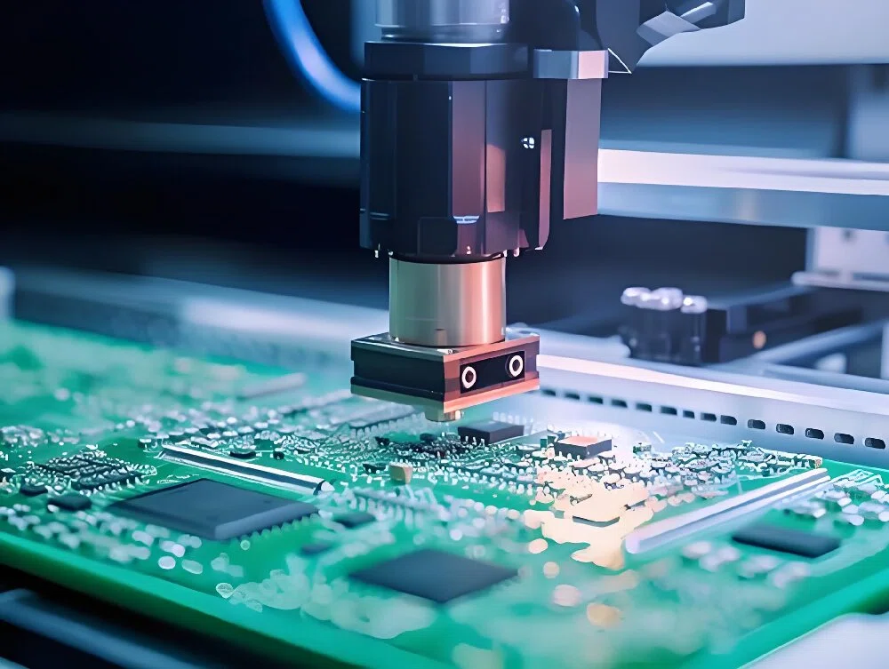
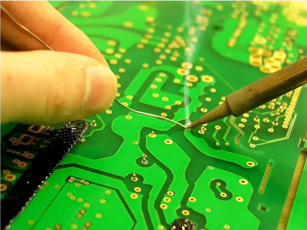
A reliable pcb module needs a production process that preserves both electrical performance and physical consistency. PCB fabrication controls such as layer registration, copper thickness, via quality, and impedance requirements become important when the module contains dense routing, high-speed signals, or RF circuits. During assembly, component placement, solder-joint quality, thermal exposure, and connector alignment can influence the finished unit’s performance.
Testing should verify the module’s defined function rather than relying only on visual inspection. Depending on its purpose, validation may include power-up checks, current consumption, output regulation, communication tests, sensor accuracy, signal measurements, or RF performance. Environmental and mechanical tests may also be appropriate for applications involving temperature changes, vibration, moisture, or repeated handling.
Clear acceptance criteria make these tests repeatable. Production records, component traceability, and documented test results help identify whether a failure originates within the module, at its interface, or elsewhere in the host system. When a module will be reused across multiple products, a controlled interface specification and consistent manufacturing process are especially valuable.
Ultimately, a pcb module succeeds when its internal circuit, external interfaces, thermal behavior, and verification process work together as a dependable functional unit. Defining these requirements before layout and assembly helps reduce integration problems, supports repeatable manufacturing, and makes the module easier to maintain throughout the product’s service life.