What is PCB Functional Testing?PCB functional testing, often called Functional Circuit Test or FCT, evaluates an assembled PCB under operating conditions that represent its intended use. The exact procedure depends on the circuit and the functions defined in its product specification.
A typical test connects the PCB to a fixture and supplies the required power and input conditions. Test equipment or software then monitors the board’s response. A communication board, for example, may be checked by sending and receiving defined data through an interface. A controller may be tested with simulated sensor inputs and measured outputs, while a power board may be checked for voltage, current, frequency, or response under a specified load.
The test therefore evaluates how the assembled circuit behaves when its different sections operate together. This is different from checking whether individual components or electrical connections meet their specified values.
The test procedure should be based on the actual requirements of the product. Input conditions, measurements, acceptable limits, and pass or fail criteria need to be defined before production testing begins. A test that checks only a small number of convenient signals may leave important functions unverified.
How PCB Functional Testing Works
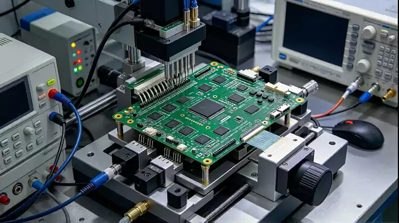
A PCB functional testing starts by establishing a controlled connection between the assembled board and the test system. Depending on the design, this may involve connectors, probes, test points, cables, or a combination of them. Power supplies provide the required operating conditions, while instruments or software generate inputs and collect the resulting measurements.
The test sequence can then examine the board in a defined order. It may begin with power-up checks and move through communication interfaces, digital inputs and outputs, analog signals, sensors, displays, motors, relays, or other functions included in the product specification. The sequence varies with the circuit architecture.
Test software is often used to control instruments, send commands to the PCB, monitor responses, compare measurements with defined limits, and record the result. Automated testing helps keep repeated production tests consistent and reduces the amount of manual observation required.
The fixture also needs to match the PCB design. Connectors, probes, and test points must be accessible, while the mechanical structure needs to hold the board securely during the test. For repeated production testing, fixture design and test software also need to support the required test time and operating conditions.
Some products require firmware-related checks as part of functional testing. The test may verify that the board boots correctly, responds to defined commands, communicates with another device, or produces the expected output after a specified input is applied. These checks can identify problems that are not apparent from component-level inspection.
What Does PCB Functional Testing Check
The scope of PCB functional testing depends on the purpose of the board. A simple control circuit may require a small number of input and output checks, while communication, industrial, automotive, or power-control boards can require a longer test sequence.
Power behavior is commonly checked during the process. The test can verify startup behavior, supply-rail voltages, and current consumption against the defined limits. Abnormal results may indicate a problem in the power section, component assembly, configuration, or circuit operation.
Communication interfaces can be tested while the board is operating. Depending on the product, the procedure may involve Ethernet, USB, CAN, UART, or other interfaces. The test can check whether the expected data is transmitted and received and whether the board responds correctly to defined commands or signals.
Inputs and outputs can also be exercised with simulated operating conditions. A test system may provide sensor signals, switches, control inputs, or other external signals and then measure the corresponding response. Outputs may include digital signals, analog voltages, control signals, displays, motors, or relays.
The acceptance limits should come from the product specification. A voltage measurement may need to remain within a defined tolerance, while a communication function may require a valid response within a specified time. Clear limits make the test results easier to interpret and provide useful information for production troubleshooting.
Functional testing can detect faults that are difficult to identify through visual inspection alone. A board may have correctly placed components and acceptable solder joints while still failing because of a firmware problem, timing issue, interface fault, or interaction between circuit sections. FCT is therefore used as a separate layer of verification in many PCB assembly test strategies.
PCB Functional Testing vs ICT
PCB functional testing and In-Circuit Testing address different parts of PCB assembly verification. ICT generally checks components and electrical nets for conditions such as opens, shorts, incorrect component values, polarity problems, and other assembly-related faults. Functional testing powers the assembled board and evaluates whether it behaves according to its intended operating requirements.
ICT can provide detailed information about component- and net-level faults, which makes it useful for identifying certain manufacturing defects. FCT examines the board while it is operating, so it can detect problems that appear only when several circuit sections work together. Firmware behavior, interface communication, timing, and system-level responses are examples of areas that may require functional testing.
The two methods can therefore be used together. ICT can identify electrical and assembly problems before functional testing, while FCT can confirm that the assembled board operates as required. The appropriate combination depends on factors such as PCB design, test access, production volume, functional complexity, and the types of failures that need to be detected.
Functional testing is easier to implement when testing requirements are considered during PCB design and assembly planning. Test points, connector access, measurement locations, firmware test modes, and fixture requirements can affect how efficiently the finished board can be tested.
A pcb functional testing is only as useful as the conditions it is designed to verify. The fixture, test software, input signals, measurements, limits, and result criteria need to correspond to the released PCB and its intended operating requirements. This keeps the test connected to the actual function of the product rather than treating it as a generic pass or fail check.