Radio frequency interference can disrupt wireless communication, distort sensitive measurements, and affect the performance of electronic circuits. Choosing the right radio frequency shielding material helps control unwanted electromagnetic energy and improves the electromagnetic compatibility of electronic equipment. However, shielding effectiveness depends on more than the material itself. Frequency range, field characteristics, enclosure geometry, electrical bonding, and openings all influence how well a shielding structure performs.
Radio frequency shielding is used in communication equipment, radar systems, medical electronics, industrial controls, wireless devices, and printed circuit board assemblies. Depending on the application, shielding may protect an individual component, isolate a sensitive circuit section, or reduce emissions from an entire electronic enclosure. Understanding the differences between available materials makes it easier to choose a solution that meets electrical requirements without adding unnecessary weight, cost, or manufacturing complexity.
How Radio Frequency Shielding Materials Control Interference
Electromagnetic shielding generally reduces unwanted energy through reflection, absorption, and, in some structures, multiple internal reflections. The contribution of each mechanism depends on the material properties, frequency, thickness, and geometry.
Conductive materials such as copper and aluminum can reflect electromagnetic energy because their mobile electrical charges respond to the incident field. Some energy also penetrates the material and is attenuated as it travels through the conductor. This attenuation is associated with the skin effect, which causes high-frequency current to concentrate near the conductor’s surface.
Magnetic shielding works differently. Materials with high magnetic permeability can redirect magnetic flux and may be useful for certain low-frequency magnetic fields. A highly conductive metal is not automatically the best choice for every magnetic shielding problem, particularly at low frequencies where magnetic permeability and field geometry can be more important.
These distinctions matter when selecting a radio frequency shielding material. A solution that performs well against high-frequency electric fields may not provide the same level of protection against low-frequency magnetic interference. The relevant frequency range and field type should therefore be established before comparing materials.
Shielding effectiveness is commonly expressed in decibels and describes the reduction in electromagnetic field or power under specified test conditions. A higher value indicates greater attenuation in that measurement context, but a single number cannot describe performance across every frequency. Results also depend on the test method, sample configuration, seams, apertures, and electrical connections.
Common Radio Frequency Shielding Materials and Their Practical Differences
Copper is widely used where high electrical conductivity is important. Copper foil, sheet, plating, and conductive layers can provide effective shielding in PCB structures, enclosures, and localized shield assemblies. Its conductivity makes it useful for many RF applications, although weight, cost, corrosion behavior, and mechanical requirements still need consideration.
Aluminum offers good electrical conductivity at relatively low weight, making it attractive for electronic housings and equipment enclosures. It can also provide useful structural rigidity and heat dissipation. However, its naturally forming oxide layer is electrically less conductive than the underlying metal, so surface treatment and reliable electrical contact at joints may be important.
Steel can provide a combination of structural strength and electromagnetic shielding. Certain steel grades are useful when magnetic properties matter, while ordinary steel may be selected for enclosure strength and cost. High-permeability nickel-iron alloys are designed for specific magnetic shielding applications, but their performance can be sensitive to mechanical processing and material condition.
Conductive coatings and paints can add a conductive surface to selected plastic housings or other nonmetallic structures. Their performance depends on coating composition, thickness, coverage, adhesion, and electrical continuity. These coatings can be useful when a lightweight or molded enclosure is required, but they should not be assumed to perform like a continuous metal enclosure without testing.
Conductive fabrics, metal meshes, and conductive elastomers are often used where flexible interfaces or removable covers are needed. They can help maintain electrical continuity across seams, access panels, or irregular mating surfaces. Their suitability depends on compression, environmental exposure, wear, contact resistance, and the size of openings in the assembled structure.
RF absorber materials serve a related but different purpose. They are designed to absorb electromagnetic energy and reduce reflections or resonances in selected situations. Absorbers may be made from engineered magnetic or dielectric materials, including specialized composites and foams. They are not interchangeable with conductive shielding materials, and their effectiveness depends on frequency, thickness, placement, and the required absorption characteristics.
Matching RF Shielding Material Selection to the Application
The best material depends on the problem that needs to be solved. For many high-frequency electronic enclosures, electrical conductivity, enclosure continuity, and control of openings are central considerations. For sensitive equipment exposed to low-frequency magnetic fields, magnetic permeability and the direction and strength of the field may carry greater weight.
Weight and thermal management can also affect the decision. A portable communication device may require a compact, lightweight shield, while industrial equipment may allow a heavier enclosure with greater mechanical rigidity. If the shield covers a heat-generating circuit, its thermal conductivity and contact with the surrounding structure may be useful, but heat dissipation must be evaluated separately from electromagnetic attenuation.
Environmental conditions should not be overlooked. Moisture, salt exposure, temperature changes, vibration, and repeated opening or closing can affect coatings, joints, gaskets, and contact surfaces. Dissimilar metals in contact may also experience galvanic corrosion under suitable environmental conditions. Material compatibility and surface protection should be considered when long-term shielding performance matters.
A practical selection process begins with the required operating frequency range and the type of interference involved. Engineers can then compare conductivity, magnetic properties, thickness, weight, mechanical strength, environmental resistance, and manufacturing constraints. The design should define a measurable shielding target under specified conditions rather than relying on broad descriptions such as “high shielding performance.”
For a radio frequency shielding material, the final choice should be based on the complete installed structure. Material datasheets provide useful starting information, but the finished enclosure or board-level shield may behave differently because of seams, contact resistance, cable penetrations, and assembly tolerances.
RF Shielding Design for PCB and Electronic Enclosures
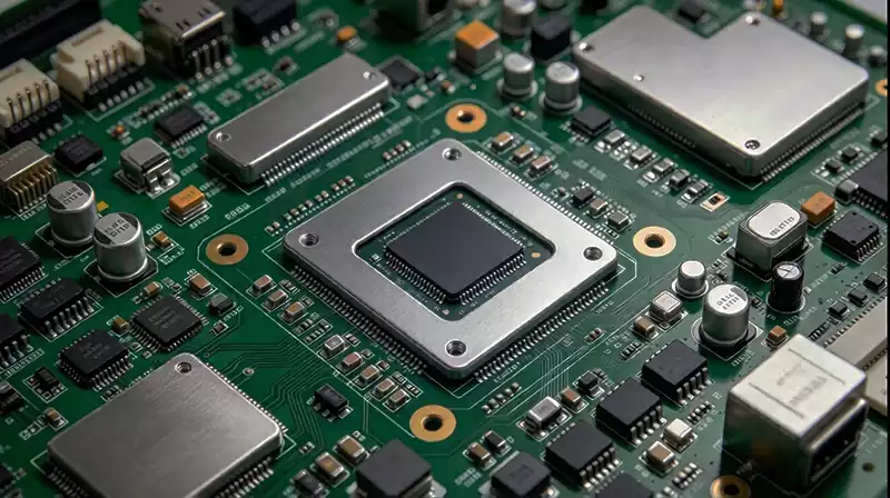
At PCB level, shielding can be applied around individual components or selected circuit sections. A metal shield can may reduce coupling between sensitive and noisy circuits, helping protect RF receivers, oscillators, amplifiers, and other susceptible components. Its effectiveness depends on the shield geometry, grounding arrangement, frequency range, and the electrical behavior of the circuit beneath it.
The PCB layout should support the intended shielding structure from the beginning. Designers may need to allocate space for shield walls, grounding pads, mounting features, and stitching vias. A poorly connected shield can introduce unwanted resonances or fail to provide the expected attenuation. The shield should also avoid interfering with component clearance, thermal paths, and required service access.
Enclosure-level shielding requires similar attention to electrical continuity. A conductive cover may perform well across its main surface yet leak energy through poorly bonded seams or large openings. Conductive gaskets can help maintain contact between mating surfaces, while cable entry points may need appropriate connector bonding or filtering. Ventilation slots and access openings must be designed with the operating frequency and mechanical requirements in mind.
Shielding is not a substitute for good circuit design. Short current loops, suitable return paths, careful component placement, appropriate grounding, and effective power-supply decoupling can reduce interference at its source. Filtering may be needed for conducted noise entering through power or signal connections, while absorber materials may help address selected resonances. The most effective approach often combines these techniques according to the actual interference mechanism.
Testing and Verifying RF Shielding Performance
A shielding design should be validated under conditions representative of the intended application. Depending on the product, evaluation may include radiated emission testing, radiated immunity testing, near-field measurements, or direct measurement of shielding effectiveness. These tests answer different questions and should not be treated as equivalent.
Radiated emission testing examines unwanted electromagnetic energy produced by the equipment. Immunity testing evaluates whether external disturbances cause unacceptable behavior. Shielding effectiveness measurements assess attenuation under a defined test configuration. The appropriate method depends on the product requirements and the relevant compliance standards.
Testing should include the assembled configuration wherever practical. Seams, fasteners, gaskets, connectors, cables, and surface finishes can influence performance, so testing a material sample alone may not predict the results of the finished product. Measurements across the required frequency range can also reveal narrow frequency bands where shielding is less effective.
If results are insufficient, engineers should identify the dominant leakage or coupling path before changing materials. Improving a seam connection, adjusting shield grounding, reducing an opening, revising the PCB layout, or adding a suitable filter may solve the problem more efficiently than simply increasing material thickness.
Selecting a radio frequency shielding material is therefore an engineering decision involving electromagnetic behavior, mechanical design, manufacturing, and verification. By matching material properties to the interference problem and validating the complete structure, designers can build electronic systems with more predictable RF performance and reliable electromagnetic compatibility.