In today’s highly digitized and interconnected world, every leap forward in electronic technology—from miniature wearable medical devices to super server clusters supporting the global AI computing power surge—relies on a common physical foundation. This foundation is neither the ever-evolving semiconductor wafers nor abstract optoelectronic algorithms, but rather a vast physical network that perfectly carries, connects, and brings life to both. In the context of modern hardware engineering, this process is given a name imbued with creativity and rigorous scientific spirit: Electronic Circuit Board Design.
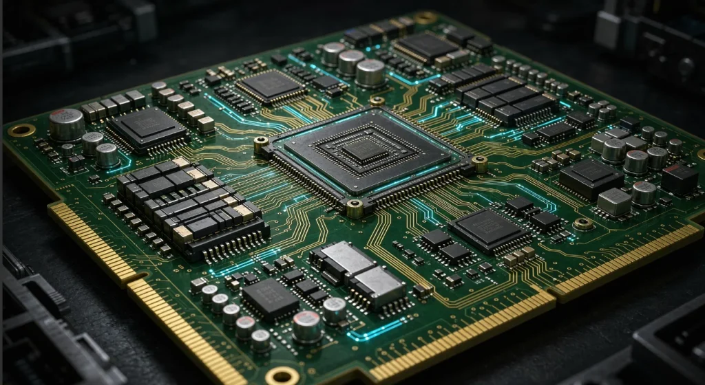
People often compare integrated circuit chips to the “brain” of electronic devices, and circuit boards to their “nervous system and meridians.” However, this analogy is somewhat simplistic. A modern, high-performance electronic circuit board design is far more than a simple connection of a few wires; it is an ultimate coordination of electromagnetic field dynamics, polymer materials science, thermodynamic heat transfer mechanisms, and precision mechanical manufacturing processes on a micrometer-scale spatial and picosecond-scale temporal scale. In the pure physical world, devoid of formulas and tables, the layout of every pad, the bend of every trace, and the division of every plane silently speaks of a rigorous engineering philosophy.
The Art of Concept Creation and Logic Capture
The birth of any great circuit board is never a matter of simply sketching on a blank physical canvas. Its starting point is a purely logical world—the origin of electronic circuit board design—the schematic capture and logic mapping stage.
In the development of a complete electronic system, the first thing a system architect needs to determine is the division of functional modules. This is similar to functional zoning in urban planning: which areas are responsible for energy conversion, which for high-speed digital computing, and which for the acquisition and amplification of weak analog signals. At this stage, engineers use specialized electronic design automation software to abstract hundreds or thousands of discrete components, complex microprocessors, power management chips, and various interfaces into graphic symbols with specific pin numbers and electrical attributes.
However, a schematic is far more than just an electrical map for humans to read. At the core of modern design tools, every graphic symbol is deeply bound to rigorous electrical rules, packaging models, material codes, and parameter attributes. When an engineer connects two pins with wires on a schematic, the system is building a vast electrical network database—a netlist—in real time in the background. Like a global scheduling table in a city’s traffic network, the netlist precisely records the topological logical relationships between tens of thousands of nodes.
In this early stage of logic creation, the core challenge of design lies in “eliminating ambiguity and ensuring logical completeness.” Circuit designers must meticulously review the drive capability, logic level compatibility, and fault protection mechanisms of every input/output port. Any logical oversight, such as an unconstrained floating input or an unreasonable pull-up resistor value, will manifest as an electrical disaster that is difficult to diagnose on the subsequent physical board. Every connection in the schematic lays an irreversible causal thread for the upcoming layout of the three-dimensional physical world.
Physical Reconstruction of Matter and Multilayer Stacking Architecture
Once the logic netlist is perfectly closed within the computer, the design work officially plunges from the abstract two-dimensional logical world into the three-dimensional physical world. The primary challenge facing engineers is determining the physical framework of the circuit board—material selection and layer stacking architecture design.
In the early stages of electronic technology development, circuit boards were mostly single-sided or double-sided, with all traces and components crammed onto the same plane or both sides. However, with the exponential increase in pin density of very large-scale integrated circuits (VLSI), two-dimensional planar space quickly became insufficient to meet the demands of massive interconnections. Multilayer circuit board design emerged to address this need. Modern high-performance circuit boards are typically constructed by alternating high-temperature bonding of dozens of extremely thin conductive copper foils with insulating dielectrics.
The core physical revolution in this complex multilayer architecture lies in the introduction of dedicated continuous power planes and continuous ground planes. These large areas of pure copper foil no longer handle sporadic signal transmission tasks but instead become low-impedance energy reservoirs and ubiquitous electromagnetic shielding. The introduction of the ground plane completely reconstructs the electromagnetic environment inside the circuit board, providing a stable reference image for high-speed signals.
The cornerstone of layered architectures is high-performance copper-clad laminate materials. The most classic and widely used is epoxy resin-fiberglass composite material. However, in designing high-frequency, high-speed, radio frequency communication, or microwave circuits, the high dielectric constant and energy loss of ordinary materials can cause severe signal attenuation, forcing engineers to turn to high-end specialty substrates such as PTFE, hydrocarbon resins, or ceramic fillers.
In layered design, “absolute symmetry” is an unshakeable engineering principle. The lamination structure of the circuit board must be based on a physical central axis of symmetry, maintaining strict physical symmetry from the thickness of the copper foil and the type of insulating prepreg to the thickness of the dielectric layer. If the layered design is off-center or asymmetrical, the circuit board will experience irreversible and severe warping during subsequent high-temperature lead-free soldering due to the natural differences in the thermodynamic expansion coefficients of the different materials. This microscopic stress imbalance will cause all subsequent automated chip surface mounting and mechanical assembly to fail.
Spatial Dynamic Equilibrium and Thermomechanical Constraints
After determining the multi-layer stacked architecture, engineers obtain a physical canvas. The next core task is component placement. There’s a widely circulated saying in electronic design: a good placement is half the battle won, while a bad placement is beyond saving.
Placement is not a jigsaw puzzle of randomly stuffing components onto a circuit board; it’s a precise planning of spatial logic. The entire circuit board needs to be divided into different physical islands based on signal characteristics and energy levels: high-voltage areas, low-voltage digital logic areas, high-frequency analog signal areas, sensitive sensor acquisition areas, and power conversion module areas that generate significant heat.
The core golden rule of placement is “following the natural signal flow.” The main processor chip should be located at the core hub, surrounded by high-speed memory and peripheral interface chips that communicate frequently with it. High-frequency RF circuits must be placed close to the antenna interface; high-frequency, high-speed signals must never be allowed to traverse the entire circuit board via long detours. By tightly clustering related components together, the physical length of traces can be minimized, reducing parasitic inductance and capacitance caused by excessively long wires at the source.
Meanwhile, layout must also compromise with harsh thermodynamic realities. Electronic components inevitably generate significant heat during operation. If high-power chips or high-power switching transistors are crammed into enclosed corners, the accumulated Joule heat can quickly trigger over-temperature protection or even thermal breakdown. Therefore, thermodynamic management must be prioritized during the layout phase. Heat-generating devices should be kept away from heat-sensitive components and preferentially placed at edges with good airflow or in locations with reserved heat-dissipating copper foil.
Furthermore, layout must be subject to stringent constraints from the macroscopic mechanical world. Circuit boards are not isolated entities; they must fit seamlessly into custom metal casings, chassis, or drone bodies. The precise coordinates of positioning holes, the physical orientation of connectors, the height limitations of large capacitors, and the ease of insertion and removal during later manual or machine maintenance are all mechanical engineering boundaries that must be repeatedly weighed during the layout phase.
The ultimate showdown between micron-level microsculpture and transmission line theory
Once the physical coordinates of the components are completely locked, the core battle of circuit board design—the routing phase—officially begins. If schematics are the skeleton and layout is the organs, then wiring is the blood vessels and nerves that carry energy and information.
In low-frequency or DC circuits, wires are simply unobstructed channels for transmitting current. However, when signal frequencies reach the gigahertz level, and signal edge transition times shorten to nanoseconds or even picoseconds, each printed conductor is no longer a simple wire, but transforms into a transmission line with distributed parameters.
Transmission lines possess distributed inductance, capacitance, and resistance characteristics, exhibiting a defined characteristic impedance. If the characteristic impedance changes abruptly along the signal transmission path (e.g., the trace suddenly narrows, encounters a via, or crosses a ground plane gap), high-frequency electromagnetic waves will be reflected at the abrupt point. This reflected wave, superimposed on the incident wave, can cause severe overshoot, undershoot, and ringing waveforms at the receiver, leading to serious misjudgments in digital logic.
To prevent signal reflection, high-end PCB designs must strictly implement impedance control. Engineers use specialized simulations to precisely adjust the trace width, copper foil thickness, and dielectric height from the reference ground plane, ensuring the characteristic impedance of the entire high-speed signal line is accurately maintained within the system standard value.
Within densely packed circuit boards, hundreds of thousands of signal lines are arranged in parallel, inevitably leading to electromagnetic coupling. A high-speed switching signal line can couple noise to adjacent parallel traces through inter-line capacitance and mutual inductance—this is the troublesome crosstalk phenomenon. To suppress crosstalk, design specifications require strict adherence to safety margins in trace spacing. For buses transmitting high-speed differential signals, differential pair wiring must be used. Differential signals utilize two equally long, closely spaced conductors to transmit complementary signals with opposite phases, eliminating common-mode noise introduced by subtraction at the receiving end. This requires the two differential lines to not only maintain perfect parallel spacing but also achieve absolute length matching when facing bends, controlling the phase difference within an extremely small micrometer-level tolerance.
In this microscopic world, current never disappears into nothingness; it must form a closed loop. For high-speed signals, the high-frequency return current will choose the reference ground plane with the lowest impedance, close to the signal line, and return along the same path directly below the signal line. If the circuit board designer arbitrarily cuts huge slots into a large ground plane for routing convenience, the return current is forced to take a long detour, crossing the gap in the ground plane. This will instantly generate a huge physical electromagnetic radiation loop on the circuit board, emitting strong electromagnetic interference and severely damaging its own signal integrity. Therefore, protecting the absolute integrity of the return path is an inviolable red line in high-end wiring design.
The ultimate battle between system-wide defense and electromagnetic compatibility
If signal lines are the nerves that transmit information, then the power distribution network is the circulatory system that maintains the life activities of the entire organism. In a complex digital system, hundreds or thousands of transistors switch on and off simultaneously, instantly drawing huge peak currents from the power network, causing the power supply voltage to drop instantly.
To tame the high-frequency transient noise of the power network, a massive number of decoupling capacitors must be densely packed on the circuit board. Decoupling capacitors act as miniature local reservoirs. When a transient high-current surge occurs within the chip, the local decoupling capacitors release charge within nanoseconds, filling the gap caused by the power supply voltage drop. During the design process, these capacitors must be physically positioned at the absolute forefront, closest to the chip’s power pins, and directly connected to the power and ground planes via extremely thick, short vias. Any excessively long leads will introduce fatal parasitic inductance, completely negating the high-frequency filtering function of the decoupling capacitors.
Simultaneously, modern electronic devices must pass extremely stringent electromagnetic compatibility (EMC) certifications, proving that they neither radiate excessive electromagnetic interference nor are immune to external electromagnetic attacks. In the final stages of circuit board design, engineers construct a defense matrix using precise shielding and grounding techniques. A dense row of metallized ground vias is placed along the edges and sensitive areas of the circuit board, stitching the top and bottom ground planes together into a Faraday cage-like closed shield, locking in edge leakage of high-frequency electromagnetic waves. Common-mode inductors, ferrite beads, and transient suppression diodes are strategically placed near all external interfaces entering and exiting the circuit board, constructing an impenetrable wall against external lightning surges and electrostatic discharges.
Design for Manufacturing: Final Review and Delivery to the Real World
When all the complex schematics, multi-layer stack-ups, microwave wiring, and electromagnetic interference (EMI) shielding are perfectly closed on the computer screen, circuit board design is not truly finished. If a drawing is flawless in the computer but cannot be manufactured with a reasonable yield on a real factory assembly line, it is still a piece of waste paper. This is the ultimate mission of design for manufacturing.
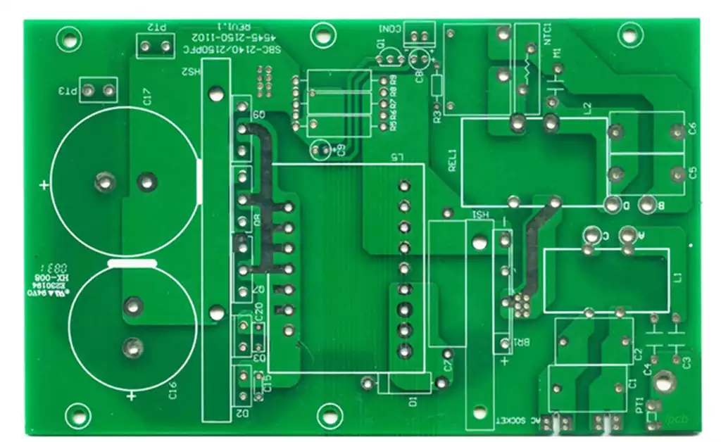
The final step in the design process is to transform the complex computer-aided design (CAD) layout files into a globally recognized standard manufacturing language. The standard format, through a series of independent layer files, precisely describes the geometric trajectory of the top copper layer, the bottom solder mask, silkscreen characters, drill coordinates, and outline, packaging all manufacturing information into a highly structured, unified database.
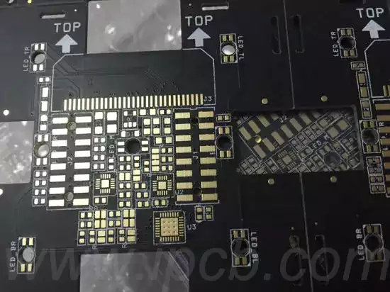
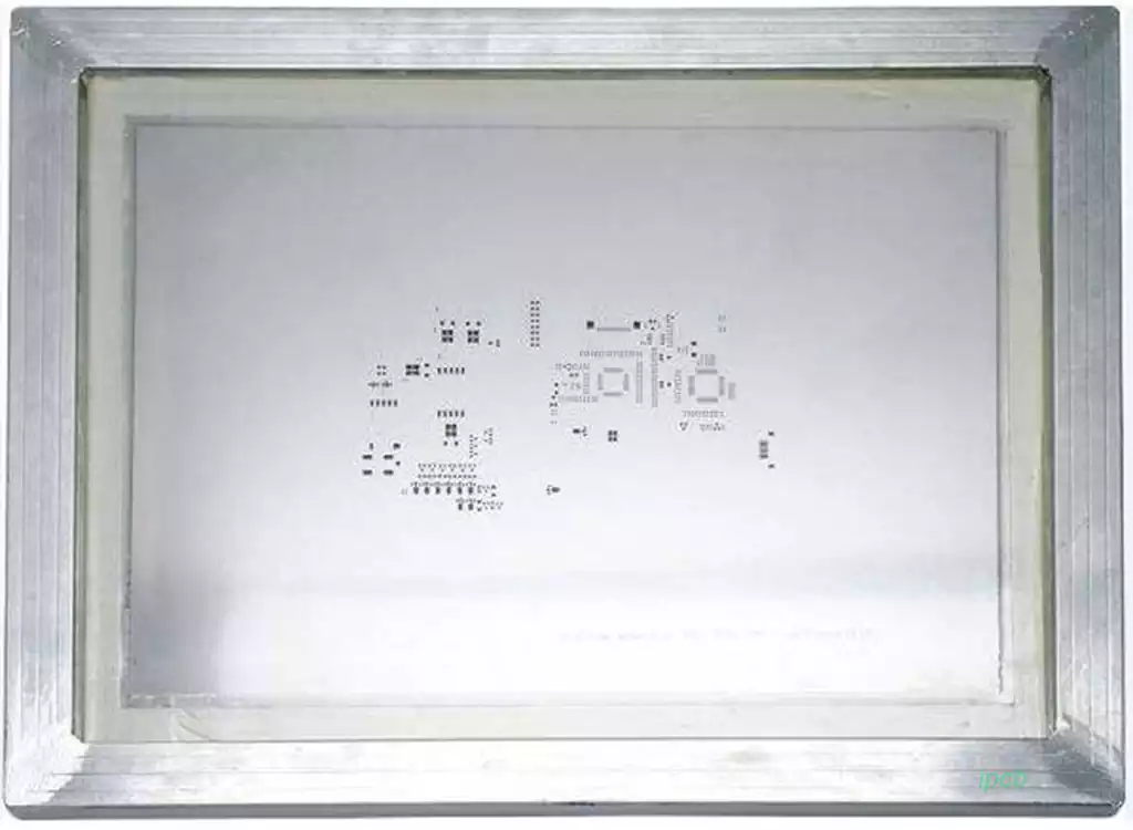
In the microscopic view of manufacturing review, the size of the solder mask opening for each pad, the spacing between each character and the pad, and the tolerance of each mechanical positioning hole must meet the limits of the PCB manufacturer’s advanced process capabilities. For example, if the bridge width of the solder resist ink is designed to be too narrow, it will break and detach during spraying, causing bridging and short circuits between adjacent pads during soldering. Conversely, if the size of the test point is smaller than the tip area of the flying probe, electrical testing will be unreliable. Furthermore, to accommodate the mechanical grippers of automated surface mount production lines, engineers must manually add standard process edges and optical positioning points to the edges of the circuit board.
Only when these rules, which incorporate the physical limits of factory manufacturing processes, are perfectly adhered to during the design phase can the circuit board confidently fly to printed circuit board manufacturers around the world, transforming into robust and durable physical hardware.
Conclusion: A Rational Poem on the Foundation of Technological Civilization
Electronic circuit board design is a rational poem spanning multiple dimensions of science. It not only requires designers to be proficient in the classical theories of electronic circuits but also to perfectly integrate the abstract fluctuations of electromagnetic fields, the thermodynamic responses of polymer materials, and the harsh boundaries of modern automated mechanical manufacturing within the confines of a micrometer-sized world.
From the logic netlists dancing on the schematic to the intricate network of impedance control transmission lines within multilayer boards; from heat dissipation in precise layout to the final quality control during manufacturing audits, every iteration of circuit board design silently supports humanity’s rapid advancement towards a future of higher computing power, wider connectivity, and ultimate reliability. A deep understanding and mastery of the underlying physics and engineering essence of electronic circuit board design is an essential path for every outstanding hardware engineer on their way to the pinnacle of technology.