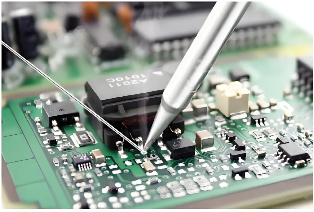
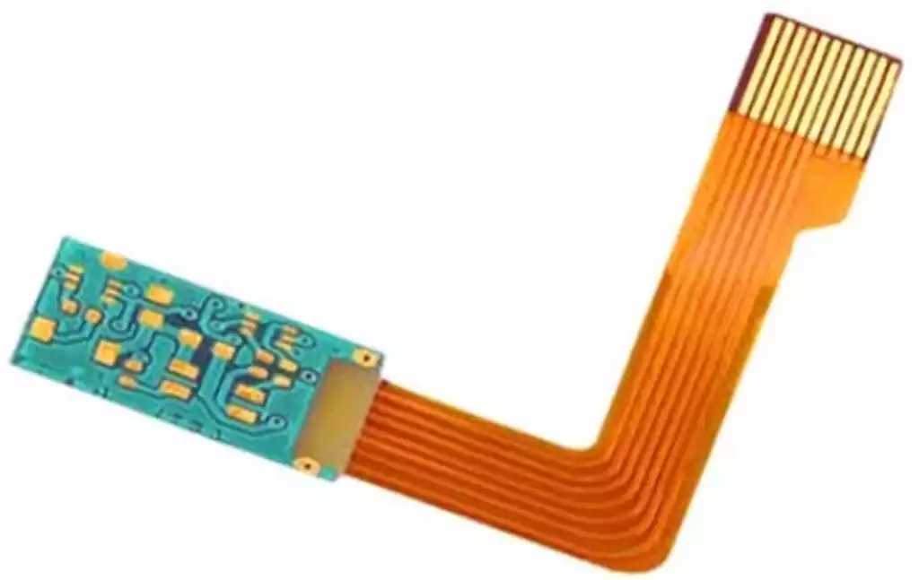
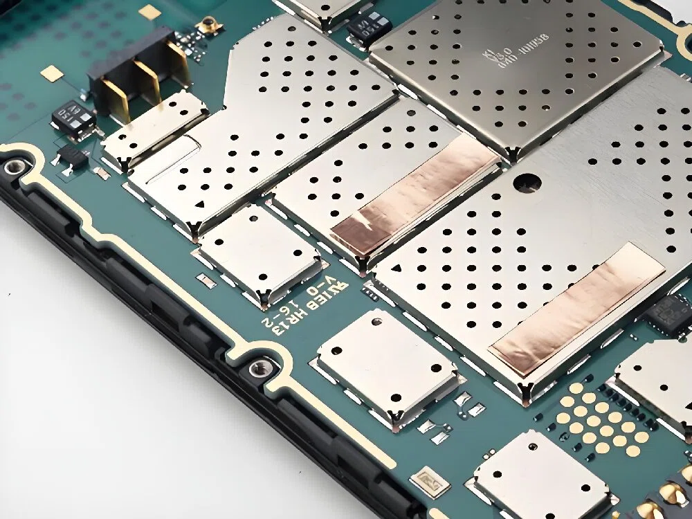
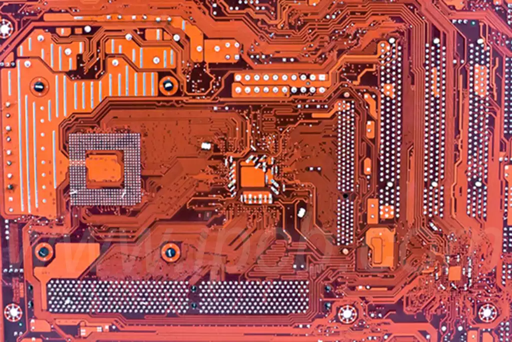
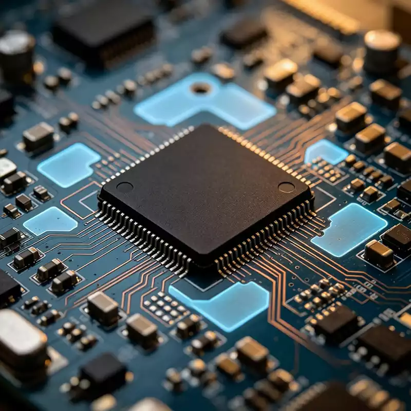
The hard disk pcb board is the core hardware that connects a hard drive to the computer’s motherboard and enables data communication between the two. It serves as the central control platform for all internal drive operations, coordinating the activities of every functional module. The design quality of the PCB, the integrity of its circuitry, and the reliability of its electronic components all have a direct impact on the drive’s overall stability. Any design flaw or circuit failure can result in a wide range of problems, including read/write errors, startup failures, communication interruptions, or complete drive malfunction.
At the center of the hard disk pcb board is the controller IC, which functions as the drive’s primary signal processing unit. Its read/write channel consists of several key functional blocks, including a preamplifier, read/write circuitry, and a clock synchronization module. The preamplifier incorporates multiple independent signal channels, each corresponding to a specific read/write head inside the drive.
Channel selection is managed by the onboard microprocessor, which coordinates communication between the controller and the individual heads. In addition to signal amplification, the preamplifier integrates current-switching and fault-detection circuits that continuously monitor the operating condition of each head. If an abnormality is detected, it immediately reports the fault to the controller, allowing the drive to initiate hardware protection mechanisms before the problem escalates.
The controller’s read/write channel operates in two distinct modes: write mode and read mode. During write operations, the controller communicates with the disk controller, receives write commands and data from the host computer, and performs the necessary data preparation before recording information onto the storage media.
During read operations, the analog signals captured by the read/write heads are first amplified and conditioned by the preamplifier before being transmitted to the PCB’s signal processing circuitry. There, the signals undergo filtering, compensation, pulse detection, and waveform correction to produce standardized digital pulses. These signals are then decoded by the disk controller and ultimately transmitted to the host computer through the drive’s external interface.
The disk controller is one of the most sophisticated and critical functional blocks on the hard disk pcb board, playing a decisive role in determining data transfer performance between the drive and the host system. It incorporates four primary communication interfaces that connect to the host computer, the onboard microprocessor, cache memory, and the internal data transfer bus, enabling efficient coordination of data flow throughout the drive.
Operating under the supervision of the microprocessor, the disk controller executes standard host commands, accesses register data, and manages essential processes such as power-on initialization and parameter configuration through the circuitry integrated on the hard disk pcb board.
Cache management is another fundamental function coordinated by the disk controller. The controller manages the onboard RAM cache through the hard disk pcb board, while the microprocessor divides the available memory into multiple independent buffer regions and records their addresses in dedicated registers. This architecture enables highly efficient parallel processing. While one portion of the cache is occupied transferring data to or from the host, other memory regions remain available for simultaneous read and write operations, significantly improving overall throughput and data processing efficiency.
The operation of the spindle motor is controlled by a dedicated motor controller located on the hard disk pcb board and supervised by the onboard microprocessor. The controller can simultaneously manage multiple motor-related functions throughout the drive. Motor operation is typically divided into three stages: startup, acceleration, and steady-state operation.
When power is applied, the reset circuitry on the PCB generates a startup signal that initiates spindle rotation and produces the required back electromotive force (BEMF). The motor then accelerates smoothly until it reaches its rated operating speed, after which it enters a stable operating state. During normal operation, the hard disk pcb board continuously monitors motor phase signals and dynamically adjusts the rotational speed to maintain precise and consistent spindle performance.
The entire power-on self-test (POST) and initialization sequence is also managed by the hard disk pcb board. Immediately after power is applied, the reset circuit sends a reset signal to the onboard microprocessor, triggering the execution of firmware stored in the ROM. During this process, temporary data stored in memory, the disk controller, and other programmable devices is cleared, restoring all hardware to a known operating state.
The system then performs a series of diagnostic checks to verify the status of critical internal circuits and detect any serious hardware faults. If no abnormalities are found, the spindle motor is started and the drive proceeds with its normal boot sequence.
As initialization continues, the PCB systematically verifies the operating status of the cache memory, disk controller, and input signal circuits. It also monitors spindle speed through pulse signals to confirm that the motor has reached its specified operating speed. Once rotational stability has been achieved, the hard disk pcb board activates both the head positioning circuitry and the disk controller, directing the actuator to move the read/write heads to their designated operating position.
At the same time, firmware data is loaded into cache memory to establish the environment required for normal read and write operations. After all self-test and initialization procedures have been completed successfully, the drive enters its ready state, continuously monitoring commands from the host computer and coordinating the operation of its onboard circuits and electronic components to execute data storage and retrieval tasks.
The hard disk pcb board is the operational control center of the entire storage device. Its performance and reliability directly determine the efficiency of data processing, the stability of drive operation, and the overall dependability of the storage system. As the foundation that integrates control logic, signal processing, motor management, power regulation, and communication, it is one of the most essential hardware components required for the normal operation of both HDDs and SSDs.