A PCB control board receives information from sensors, processes that information and sends commands to motors, relays, valves, displays or communication interfaces. This ability to make decisions and control external devices distinguishes it from a circuit board that only provides electrical connections or performs one fixed function.
Control boards are used in industrial machinery, motor drives, household appliances, medical instruments, automotive electronics and communication equipment. The application may change, but the engineering challenge remains similar: sensitive input signals and digital processing must operate reliably beside switching power, high-current loads and electrically noisy external connections.
For that reason, reliability in a PCB control board depends on more than selecting a microcontroller and completing the schematic. Power architecture, grounding, protection, thermal paths, component placement and functional testing must be designed as one coordinated system.
From Inputs to Controlled Outputs
The basic function of a PCB control board is to connect three stages: input acquisition, decision-making and output control.
Inputs may come from temperature sensors, pressure transducers, encoders, switches, current transformers or communication networks. The controller converts these signals into usable data, applies programmed logic and determines the required output. Driver circuits then operate motors, contactors, solenoids, heaters, pumps or other equipment.
This structure explains why a control board is usually more functionally complex than an ordinary interface PCB. It does not simply carry signals. It must determine when an output should change, how quickly it should respond and what should happen when a sensor or load behaves abnormally.
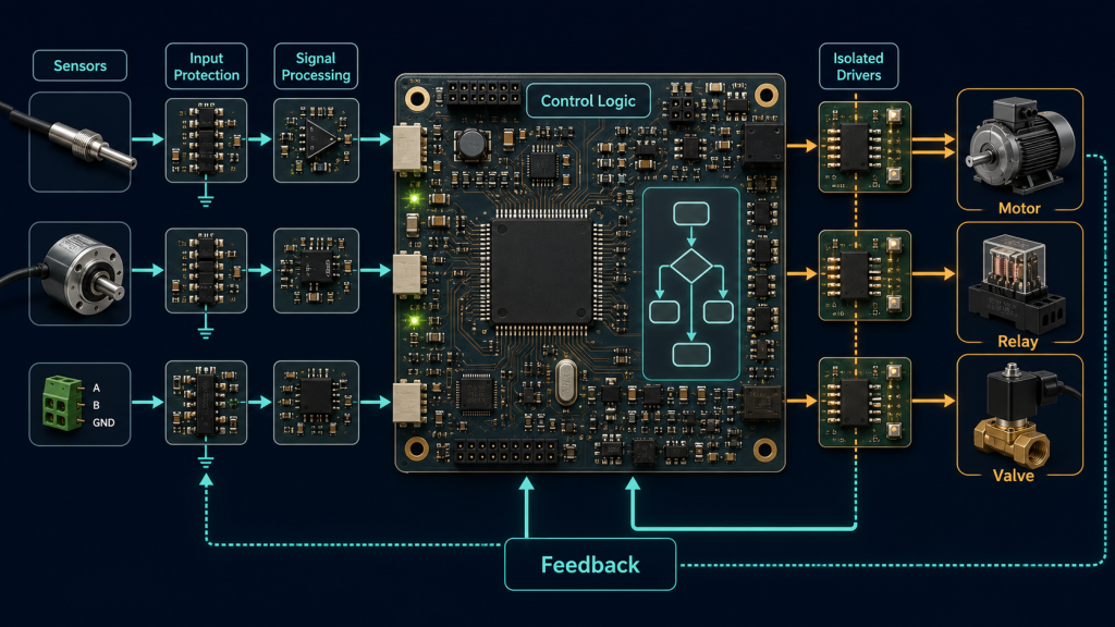
The electronics may be divided between a main control section and one or more driver or interface boards. A compact appliance might integrate every function on a single PCBA control board, while industrial equipment may separate the processor, power drivers and operator panel to improve thermal performance, isolation or serviceability.
Regardless of physical arrangement, signals entering the PCB control board need defined voltage ranges, filtering and fault protection. Outputs require adequate current capacity, transient suppression and feedback so that the controller can detect whether the command was executed correctly.
Power and Grounding Determine Control Stability
Many control-board failures appear to be software problems but originate in the power and grounding system. A processor that resets when a relay changes state, an analogue input that becomes unstable when a motor starts or a communication link that fails during load switching can all result from poor current-return control.
The board usually contains several power domains. Logic circuits may operate at 3.3 V or 5 V, while relays, valves and motors use higher voltages and currents. Analogue sensing circuits may require a quieter supply than the processor or communication section.
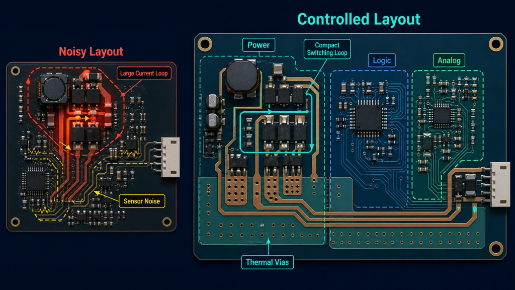
These domains should not be separated blindly, but their current paths must be understood. High-current switching loops should remain compact and should not share narrow return paths with sensor references. Decoupling capacitors need short connections to the relevant device pins, and bulk capacitance should be positioned where load changes enter the board.
Within a PCB control board, high-current drivers and switching converters should be kept away from analogue sensors, oscillators and communication transceivers. A continuous reference plane can provide a low-impedance return path, but component placement must prevent switching current from flowing through sensitive sections of that plane.
Grounding errors can produce unstable readings and even disturb microcontroller operation in industrial acquisition and control systems. Analog Devices notes that incorrect system grounding may appear as noisy sensor measurements or processor code faults rather than as an obvious power failure. Analog Devices grounding guidance
The power-entry circuit also needs to reflect the installation environment. Reverse-polarity protection, overvoltage protection, surge suppression and input filtering should be selected according to the expected source and external cable exposure. Protection parts are most effective when they are placed close to the connector and connected through short, direct current paths.
Motor and Power Loads Create the Hardest Layout Problem
Motor controllers, solenoid drivers and power converters place the greatest electrical and thermal stress on a control board. Fast voltage transitions generate electromagnetic interference, while high current produces heat in copper traces, switching devices, connectors and current-sensing components.
The switching loop should be made as small as practical. Gate-drive paths need controlled routing, bootstrap and decoupling components must remain close to the driver, and current-sense connections should avoid carrying power-stage voltage drops into the measurement circuit.
Texas Instruments identifies grounding, high-current routing, thermal design and noise reduction as central layout considerations for motor-driver boards. Improving these conditions after the PCB layout and mechanical design have been finalized is substantially more difficult than controlling them during placement and routing. TI motor-driver layout guidance
Thermal design cannot be reduced to choosing a larger copper trace. Switching devices may require copper spreading areas, thermal vias and a defined path into an enclosure or heat sink. Connectors must be rated for the sustained load, not merely the nominal current shown in the schematic.
The switching performance of the PCB control board should also be evaluated during acceleration, braking, reversing and stalled-load conditions. These operating states can create current and voltage stress that does not appear during an unloaded bench test.
Protection should respond at both hardware and firmware levels. Hardware current limiting or shutdown can react quickly to a serious fault, while firmware can monitor temperature, current, speed and command consistency over longer periods. A design that depends entirely on software may not respond quickly enough to a switching-device fault.
External Interfaces Need Defined Protection Boundaries
Control boards rarely operate in isolation. Cables connect them to sensors, motors, displays, power sources and communication networks. These cables can carry electrostatic discharge, surge energy, common-mode noise and ground-potential differences into the electronics.
RS-485, CAN, Ethernet and other external interfaces require protection matched to their voltage range and data rate. A protective device with excessive capacitance may distort a high-speed signal, while a device with an unsuitable clamping voltage may fail to protect the transceiver.
Where equipment sections operate at substantially different ground potentials, galvanic isolation may be necessary. Isolation must be treated as a complete boundary that includes the signal path, isolated power supply, creepage distance, clearance and PCB layout. Adding a digital isolator without controlling coupling across the rest of the board does not create a reliable barrier.
The communication section should also be positioned so that transient current returns toward the connector or chassis reference rather than crossing the logic area. Proper PCB choices around isolation devices can materially reduce radiated emissions, according to Analog Devices’ guidance on isolated interface layout. Analog Devices isolation and emissions guidance
Manufacturing Quality Must Protect the Design Intent
A well-designed schematic can still produce an unreliable assembly if component orientation, solder volume, thermal balance or cleanliness varies during production.
Large terminals, relays, transformers and power components may require through-hole assembly after SMT. Their solder joints must withstand cable insertion, vibration and thermal cycling as well as carry electrical current. Excess solder does not automatically create a stronger connection; hole fill, wetting, lead condition and thermal profile need controlled acceptance criteria.
Small analogue components present a different risk. Incorrect values in feedback, filtering or current-sensing networks may allow the board to start while changing its control accuracy. Automated optical inspection can confirm placement and polarity, but it may not identify every wrong value or hidden solder joint.
The manufacturing quality of a PCB control board should therefore be verified through complementary methods. AOI can inspect visible SMT features, X-ray can examine concealed joints where required, and electrical testing can confirm selected networks. IPC identifies J-STD-001 as a major process-control standard for soldered assemblies and IPC-A-610 as a widely used acceptance standard for completed electronic assemblies. IPC electronics manufacturing standards
Revision control is equally important. Control products often have several hardware and firmware versions in production simultaneously. The BOM, Gerber data, placement file, test program and firmware package must all correspond to the same approved revision.
Functional Testing Must Exercise the Control Loop
Powering the board and confirming that the microcontroller starts does not prove that the control function works. A complete test plan for the PCB control board should stimulate representative inputs, execute the programmed logic and verify the resulting outputs.
For a motor controller, this may include direction, speed feedback, current limiting and fault shutdown. An appliance controller may require sensor simulation, relay operation, display communication and user-interface checks. An industrial controller may need analogue input accuracy, isolated communication and output-load verification.
Testing should include transitions rather than only steady states. Startup, shutdown, rapid load changes, communication loss and sensor disconnection often reveal problems that remain hidden during normal operation.
Firmware programming must also remain traceable. The hardware revision, firmware version and calibration data should be recorded with the production batch or serial number. When field behavior changes, this record makes it possible to distinguish a software issue from an assembly or component problem.
A test fixture should reproduce electrical loading without introducing new instability. Connector wear, fixture resistance and probe contact can gradually alter results, so fixture maintenance and validation belong in the production process.
Environmental Protection Depends on the Application
The protection required by a PCB control board depends on where the finished equipment operates. A board sealed inside a household appliance faces different risks from one mounted near a motor, exposed to condensation or installed inside a vehicle.
Temperature range affects semiconductors, capacitors, connectors and solder joints. Vibration influences heavy components and cable connections. Humidity and contamination can reduce surface insulation resistance or promote corrosion.
Conformal coating can improve resistance to moisture and contamination, but coating material and application method must be validated for the actual environment. Connectors, switches, programming contacts, heat-transfer surfaces and other keep-out areas require controlled masking.
Coating should not be applied over an inadequately cleaned assembly. Trapped process residue can continue to support leakage or corrosion beneath the coating. IPC guidance emphasizes that coating performance depends on material selection, application and verification rather than on the presence of a coating layer alone. IPC conformal coating guidance
Bringing Design and Production Together
Reliable control electronics require the design team and manufacturer to review the same operating conditions. Input voltage, load current, switching frequency, sensor accuracy, communication distance, environment and test coverage should be defined before production tooling is finalized.
iPCB can support a PCB control board through PCB fabrication, component sourcing, PCBA, firmware programming and application-specific functional testing. Reviewing high-current paths, sensitive measurement circuits, protection components and test access before production helps preserve the original control strategy through assembly.
The objective is not merely to manufacture a board that powers on. Production must preserve the signal integrity, thermal paths, protection boundaries and feedback behavior on which the control system depends.
Reliable Control Starts at Board Level
A control board acts as the decision center of an automated product, but intelligence alone does not make it reliable. Stable power, controlled grounding, protected interfaces, adequate thermal paths and representative functional testing determine whether programmed decisions become dependable physical actions.
The long-term reliability of a PCB control board is established when schematic design, PCB layout, assembly control and system testing are treated as one engineering process. That approach allows the same control architecture to operate consistently in industrial equipment, motor systems, appliances and other automated products without turning the article into a catalogue of unrelated applications.