Testing an electronic circuit board is an important step in electronics development, troubleshooting, and manufacturing. A board may look perfectly normal while still having a short circuit, broken connection, incorrect component, damaged solder joint, unstable power rail, or signal problem that prevents it from working correctly.
The right way to test a electronic circuit board depends on what you are trying to verify. A basic diagnostic may only require visual inspection and a digital multimeter, while a complex production board may require automated optical inspection, flying probe testing, in-circuit testing, X-ray inspection, and functional testing.
A practical circuit board testing process usually starts with simple checks before moving to powered measurements and more advanced equipment. This approach reduces the risk of damaging the board and makes it easier to identify the source of a fault.
What Should You Check on an Electronic Circuit Board?
Before testing an electronic circuit board, it helps to understand the different types of problems that may occur.
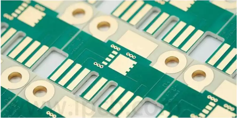
A electronic circuit board can have physical defects such as cracked traces, damaged pads, solder bridges, missing components, incorrect component placement, or poor solder joints. These problems are often related to manufacturing or assembly.
Electrical problems can include open circuits, short circuits, incorrect resistance, abnormal voltage, unstable power rails, or unwanted connections between different nets.
There can also be functional problems. In this case, the board may pass basic continuity and voltage checks but still fail to perform its intended function. A communication interface may not transmit data correctly, an oscillator may generate an incorrect waveform, or a processor may fail to start even though the main supply voltage appears normal.
For this reason, testing should progress from basic physical and electrical checks toward functional verification.
Start With a Visual Inspection
The first step in testing a circuit board should normally be a careful visual inspection. It does not require sophisticated equipment, but it can reveal many obvious assembly and physical problems before power is applied.
Inspect the electronic circuit board under good lighting and use magnification when necessary. Look for solder bridges between adjacent pins, missing components, incorrectly oriented diodes or ICs, damaged connectors, cracked components, lifted pads, burned areas, discoloration, and damaged traces.
Pay particular attention to areas with fine-pitch components. Small solder bridges can be difficult to see with the naked eye but may create a short circuit between power or signal connections.
For assembled PCBs, automated optical inspection (AOI) is commonly used in manufacturing to detect visible assembly defects. AOI can inspect component placement and soldering conditions at a scale and speed that are difficult to achieve through manual inspection alone.
A visual inspection should also compare the physical board with the schematic, PCB layout, or assembly documentation when those documents are available.
Test the Circuit Board Without Power
Before applying power to an unfamiliar or potentially defective board, perform basic electrical checks with the power disconnected.
This is particularly important when testing a newly assembled PCB or troubleshooting a board that has an unknown fault. Applying power to a board with a serious short circuit can damage components and make the original problem harder to diagnose.
A digital multimeter can be used to check resistance, continuity, and diode junctions while the board is unpowered.
One of the most useful checks is measuring resistance between each main power rail and ground. A very low resistance may indicate a short circuit, although the expected reading depends on the actual circuit. Some boards naturally have low-resistance paths between power and ground because of regulators, capacitors, semiconductor devices, or other components.
Therefore, a low resistance reading should be treated as a signal for further investigation rather than automatically interpreted as a fault.
How to Test a Circuit Board for Short Circuits
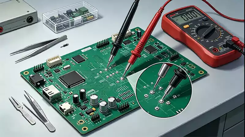
To check for a possible short circuit, set a digital multimeter to resistance or continuity mode with the PCB disconnected from its power source.
Place one probe on the ground reference and the other on the power rail being investigated. Repeat the measurement for the main supply rails and any other nets where a short is suspected.
A continuity beep or very low resistance can indicate an unintended connection, but the result must be interpreted according to the circuit design. Some components naturally provide a conductive path between two points.
If a short is confirmed, inspect the associated area for solder bridges, misplaced components, damaged ICs, or incorrect assembly.
For difficult faults, a controlled low-voltage current injection method can sometimes help locate a short by identifying an area that becomes warmer than the surrounding board. This technique should only be used with appropriate current limits and an understanding of the circuit because excessive current can cause additional damage.
How to Test electronic circuit board Continuity
A continuity test checks whether two points that should be electrically connected actually have a conductive path between them.
With the board powered off, place one multimeter probe at one end of the trace or connection and the other probe at the corresponding point shown on the schematic or PCB layout.
A low resistance generally indicates that the connection is present. An open reading can indicate a broken trace, poor solder joint, missing connection, damaged via, or another interruption in the electrical path.
Continuity testing is especially useful for checking suspected broken traces and solder connections during prototype development and troubleshooting.
For production testing, however, manually checking every connection is impractical on complex boards. Automated electrical testing methods such as flying probe and ICT are designed to test many connections more efficiently.
Test Individual Components on the Board
A circuit board can also be tested by checking individual components, although measurements made while components remain soldered to the PCB must be interpreted carefully.
Resistors
A multimeter can measure resistance across a resistor. Compare the measured value with the component’s expected value and tolerance.
However, other components connected to the same circuit can create parallel paths and affect the measurement. If the reading appears abnormal, the resistor may need to be isolated from the circuit before making a definitive measurement.
Diodes
A multimeter’s diode-test mode can be used to check many standard diodes and semiconductor junctions.
A healthy diode normally shows a forward voltage in one direction and a much higher resistance or open reading in the opposite direction. The exact forward voltage depends on the device type.
Capacitors
Capacitors can be more difficult to evaluate with a basic multimeter because the surrounding circuit can influence the measurement.
An LCR meter or dedicated component tester can provide more useful information about capacitance and, depending on the instrument, equivalent series resistance (ESR).
Always discharge capacitors before performing resistance or continuity measurements, especially on boards containing power supply circuits.
Transistors and ICs
Basic multimeter measurements can sometimes identify damaged semiconductor junctions or obvious shorts, but they generally cannot confirm whether a complex integrated circuit is functioning correctly.
For processors, controllers, communication ICs, and other complex devices, testing power rails and signal behavior is usually more useful than attempting to test the IC as a simple individual component.
Power Up the Board Carefully
After completing the basic unpowered checks, the next stage is to apply power under controlled conditions.
For a prototype or unknown board, a bench DC power supply with adjustable current limiting can provide an additional layer of protection during initial power-up.
Set the supply to the required voltage and use a conservative current limit appropriate for the board. Monitor the supply current as the board starts.
An unexpectedly high current draw can indicate a short circuit, incorrect component placement, damaged semiconductor, incorrect power connection, or another fault.
If the power supply immediately enters current limiting, do not simply increase the current limit and continue testing. Turn the power off and investigate the reason for the abnormal current.
Measure the Power Rails
Once the board is powered safely, use a multimeter to measure the main supply rails.
Check the voltage at the input and at important points throughout the power distribution system. Compare the measured values with the circuit schematic, component specifications, or design requirements.
For example, a board may have several rails generated from a single input, such as 5 V, 3.3 V, or lower-voltage supplies for digital and analog circuits. A missing or incorrect rail can prevent the rest of the circuit from operating correctly.
Power measurements can also help narrow down the location of a fault. If the input voltage is correct but a downstream rail is missing, the investigation can focus on the corresponding regulator, enable signal, protection component, load, or shorted net.
Use an Oscilloscope to Test Signals
A multimeter is useful for measuring steady-state voltage and resistance, but it cannot show the complete behavior of a rapidly changing signal.
An oscilloscope is therefore an important tool when testing an electronic circuit board that contains clocks, switching regulators, communication interfaces, PWM signals, oscillators, or high-speed digital circuits.
An oscilloscope can show whether a signal has the expected amplitude, frequency, timing, duty cycle, rise time, and waveform shape.
For example, if a microcontroller does not communicate with another device, checking the relevant clock and data signals with an oscilloscope can help determine whether the problem is related to the power supply, clock generation, signal integrity, or another part of the circuit.
The oscilloscope is also useful for checking power supply ripple, switching regulator behavior, startup sequences, and unexpected oscillations.
Check the Board’s Functional Operation
Electrical measurements alone do not prove that a circuit board works correctly.
Functional testing verifies whether the complete board performs the tasks it was designed to perform. The exact test depends on the application.
A communication board may need to transmit and receive data through its intended interfaces. A motor control board may need to generate the correct control signals. A power management board may need to provide stable output under different loads. A sensor board may need to detect and process the expected input.
Functional testing therefore connects the electrical measurements with the actual purpose of the product.
A board can pass continuity checks and have correct supply voltages while still failing functional testing because of firmware, timing, signal integrity, configuration, or component-level problems.
Common Professional PCB Testing Methods
For prototype troubleshooting, manual measurements may be sufficient. Production environments often require more structured and automated testing methods.
Automated Optical Inspection
Automated Optical Inspection, or AOI, uses cameras and image-processing techniques to inspect PCB assemblies.
It can identify issues such as missing components, incorrect placement, solder bridges, and other visible assembly defects.
AOI is particularly useful during PCB assembly because it can inspect large numbers of boards consistently and quickly.
In-Circuit Testing
In-Circuit Testing (ICT) uses electrical access points to check components and interconnections on an assembled PCB.
Depending on the test system and board design, ICT can identify manufacturing problems such as opens, shorts, incorrect component values, and other electrical defects.
ICT is particularly suitable when the production volume justifies the development of a dedicated test fixture.
Flying Probe Testing
Flying probe testing uses movable probes to contact selected points on a PCB rather than relying on a dedicated fixed fixture.
This makes it useful for prototypes, small production runs, and designs that change frequently. It generally requires less fixture investment than traditional ICT, although testing can take longer because the probes move between individual test points.
X-Ray Inspection
X-ray inspection is useful when important solder joints or connections cannot be inspected directly from the surface.
It is particularly relevant to assemblies containing components such as BGA packages, where many solder joints are hidden beneath the component.
X-ray inspection can reveal internal soldering problems that visual inspection or standard optical inspection may not detect.
Boundary Scan Testing
Boundary scan, commonly associated with JTAG-compatible devices, can test certain digital interconnections through supported integrated circuits without requiring direct physical access to every connection.
It can be valuable for densely populated boards where conventional probing is difficult. However, its coverage depends on the devices and connections that support boundary scan, so it does not replace all other PCB testing methods.
Bare PCB Testing vs PCBA Testing
It is important to distinguish between testing a bare PCB and testing an assembled electronic circuit board.
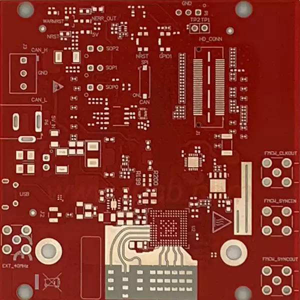
A bare PCB has no electronic components installed. Testing at this stage focuses mainly on the physical and electrical integrity of the board itself. Electrical testing can verify that required copper connections are present and that unintended shorts do not exist.
A PCBA contains components and soldered connections. Its testing requirements are much broader because the goal is to verify not only PCB connectivity but also assembly quality and circuit operation.
For a PCBA, the testing sequence may include AOI, X-ray, flying probe or ICT, power-up testing, and functional testing depending on the product and production requirements.
How to Choose the Right Circuit Board Testing Method
There is no single testing method that can detect every possible PCB defect.
For a prototype, visual inspection, a digital multimeter, bench power supply, and oscilloscope may provide most of the information needed for initial troubleshooting.
For a small production run, flying probe testing can provide automated electrical verification without requiring the same fixture investment associated with some ICT setups.
For higher-volume production, ICT, AOI, functional testing, and other automated methods can be combined to improve test coverage and repeatability.
The correct strategy should therefore be based on the type of board, production volume, expected failure modes, test access, required coverage, and cost of undetected defects. Recent PCB testing guidance similarly emphasizes matching each test method to the defects it can actually detect rather than assuming that one test provides complete coverage.
Common Mistakes When Testing a Circuit Board
One common mistake is applying power before checking for obvious shorts. A simple resistance check can sometimes identify a serious problem before it causes additional damage.
Another mistake is relying on a single measurement. A normal supply voltage does not prove that a circuit is functioning, just as a continuity beep does not prove that a high-speed signal is operating correctly.
Testing components while they remain connected to a complex circuit can also produce misleading measurements because current can flow through other components and create parallel paths.
Another issue is failing to compare measurements with the actual circuit design. A resistance or voltage value has meaning only when it is considered in the context of the schematic, expected operating conditions, and component specifications.
For production boards, relying only on functional testing can also leave manufacturing defects undetected. A layered approach that combines inspection, electrical testing, and functional verification can provide broader coverage.
A Practical electronic circuit board Testing Sequence
For general troubleshooting, a useful testing sequence is to begin with the board documentation and a visual inspection. Next, keep the board unpowered while checking for suspected shorts, continuity problems, and obvious component issues.
After those checks pass, apply power through a controlled source and monitor current consumption. Measure the major power rails and confirm that the expected voltages are present.
The next step is to check important signals with an oscilloscope or other appropriate instrument. Finally, perform a functional test to confirm that the board behaves as intended under its normal operating conditions.
For production, the sequence may be expanded to include bare-board electrical testing, SPI or AOI, X-ray inspection, flying probe or ICT, functional testing, and reliability testing according to the product requirements.
The purpose of this layered approach is simple: each stage should detect a different class of potential failure rather than repeating the same test.
Knowing how to test an electronic circuit board requires more than checking whether the board powers on. A reliable test process examines the physical condition of the PCB, verifies electrical connections, checks power rails, evaluates important signals, and confirms the final function of the circuit.For basic troubleshooting, visual inspection, a digital multimeter, a current-limited power supply, and an oscilloscope can provide a strong starting point. More advanced PCB testing methods such as AOI, flying probe, ICT, X-ray inspection, and boundary scan are useful when boards become more complex or when production volumes require greater automation.