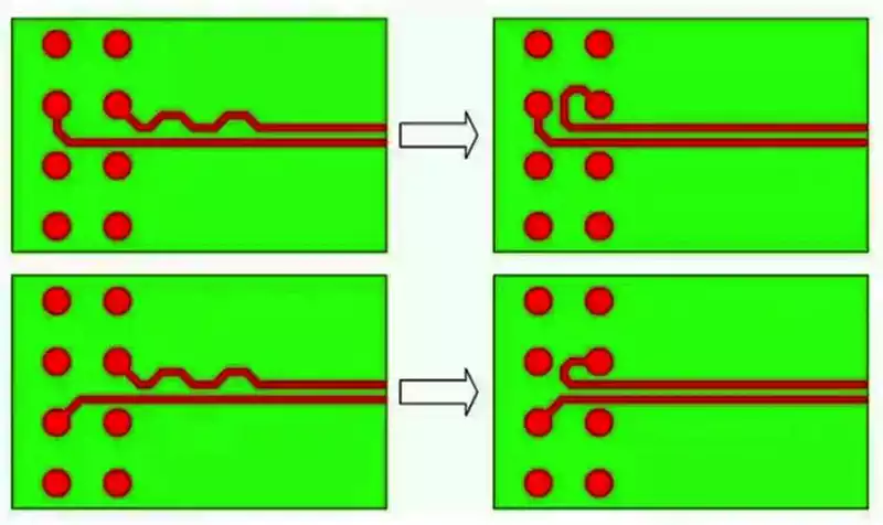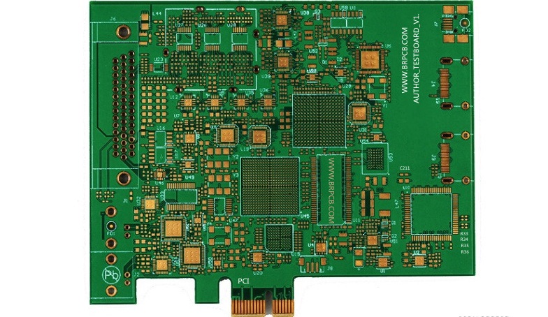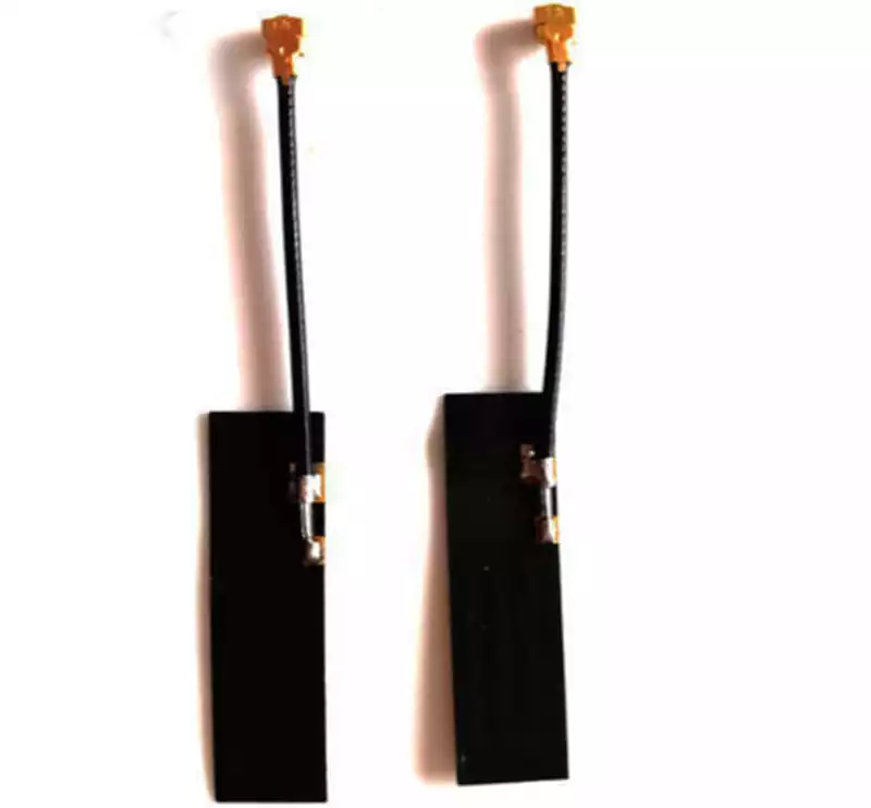
A pcb board wire is an important part of many electronic assemblies because it provides an electrical connection between a printed circuit board and other parts of a device. While copper traces form the conductive paths directly on the board, insulated wires extend those connections to external components, power sources, sensors, switches, motors, and other electronic modules. The way these wires are selected, positioned, and connected affects not only electrical performance but also the assembly process, mechanical stability, and long-term reliability of the finished product.
PCB board wiring requirements vary considerably between applications. A compact consumer device may use short, lightweight wires to connect a display or battery, whereas industrial equipment may require thicker conductors to carry higher currents over longer distances. Some products need permanent connections that remain untouched throughout their service life, while others require detachable wiring for maintenance or component replacement. Understanding these differences helps engineers determine the appropriate wire construction, termination method, and PCB layout before manufacturing begins.
PCB Board Wire Construction and Electrical Requirements
A typical PCB board wire consists of a conductive core surrounded by an insulating layer. Copper is commonly used because of its good electrical conductivity and flexibility. The conductor may consist of a single solid wire or multiple fine strands twisted together. Solid conductors can provide a stable shape for certain fixed installations, while stranded wires are generally more flexible and better suited to applications involving movement or repeated bending.
The insulation protects the conductor from accidental contact with other conductive parts and helps prevent short circuits. Common insulation materials include PVC, silicone, and other engineering polymers. Their properties differ in terms of temperature resistance, flexibility, chemical resistance, and environmental durability. For example, silicone-insulated wires may be useful in applications requiring greater flexibility across a wide temperature range, while other insulation materials may be selected for cost, abrasion resistance, or specific installation conditions.
Conductor size is another essential consideration. Wire gauge influences electrical resistance, current-carrying capability, flexibility, and the physical space required for installation. If a wire is too thin for its operating current, resistive heating and voltage drop may become excessive. A thicker conductor can reduce resistance, but it may also require a larger connector terminal and more space inside the product enclosure. Engineers therefore need to evaluate current, wire length, allowable temperature rise, and installation conditions together rather than choosing a wire based on physical appearance alone.
Voltage and signal characteristics also influence wire selection. Power conductors must have suitable insulation and current capacity, while signal wires may need additional protection against electromagnetic interference. In sensitive electronic equipment, twisted-pair construction, shielding, or carefully arranged grounding connections can help reduce unwanted noise. The appropriate solution depends on signal frequency, cable length, surrounding electrical activity, and the circuit’s tolerance for interference.
Connecting Wires to PCB Assemblies
The connection between a wire and a PCB must provide dependable electrical contact while remaining mechanically stable. One approach is to solder the stripped conductor directly to a designated pad on the board. This method can reduce component count and is useful for simple or low-volume assemblies. However, the wire must be properly prepared, and the solder joint should not carry excessive mechanical stress. Repeated pulling or bending near the connection may damage the joint or separate the copper pad from the board.
For applications that require easier installation and servicing, a dedicated wire-to-board connector is often more appropriate. The PCB side usually contains a header or socket, while the wire side uses metal terminals fitted into a matching housing. These terminals are commonly attached through crimping, which compresses the terminal around the conductor to establish electrical and mechanical contact. A properly designed connector allows the cable to be disconnected without desoldering individual wires.
Terminal blocks offer another practical option, particularly in industrial control panels, power interfaces, and equipment that may need field wiring. Depending on the design, conductors are secured by screws or spring-loaded contacts. This arrangement can make installation and maintenance more convenient, especially when technicians need to connect several individual wires.
The selected termination method should match the product’s operating conditions. A wire inside a stationary electronic device may only require a simple soldered connection, whereas equipment exposed to vibration may need a locking connector and additional cable support. The number of connection cycles, available installation space, wire gauge, and required assembly speed should also be considered.
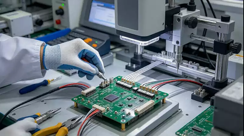
PCB Layout and Wire Routing
Wire connections should be considered during PCB layout rather than added after the circuit design is complete. Connector footprints need to match the selected component’s dimensions, pin spacing, mounting structure, and orientation. Engineers should leave enough space around each connection point for wire insertion, soldering equipment, inspection, and future servicing. If the connector is positioned too close to the edge of the board or adjacent components, installation may become difficult and mechanical interference may occur.
The routing of wires outside the PCB board is just as important as the copper layout on the board. Power cables should be kept away from sensitive signal wiring when possible, particularly when switching circuits, motors, or other sources of electrical noise are present. Where signal integrity is important, grounding and shielding arrangements should be designed to provide suitable return paths and reduce interference. Wires should also avoid sharp edges, hot components, moving mechanisms, and areas where the insulation could be damaged.
Mechanical support helps prevent connection failures. A cable that hangs freely from a small PCB connector can place continuous force on the solder joints and board pads. Cable clamps, tie-down points, enclosure channels, and strain-relief structures can reduce this stress. For products exposed to vibration or frequent movement, the cable should be routed with an appropriate bend radius and secured so that movement does not concentrate at the termination point.
Manufacturing and Quality Inspection
Consistent manufacturing is necessary to ensure that every wire connection performs as intended. Before assembly, conductors should be cut to the required length and stripped without damaging the copper strands. Excessive stripping can expose too much conductor and increase the risk of short circuits, while insufficient stripping may prevent a secure terminal connection. Crimped terminals require compatible tooling and the correct combination of wire size and terminal design.
Soldering quality also affects connection reliability. The conductor and PCB pad must form a proper solder joint without excessive solder, insufficient wetting, or unintended contact with neighboring pads. During inspection, manufacturers can check for loose strands, damaged insulation, incomplete crimps, incorrect pin assignments, and visible solder defects. Continuity testing helps confirm that the intended electrical paths are complete, while insulation testing may be required to verify separation between circuits.
For applications with demanding operating conditions, additional validation may include contact resistance measurements, mechanical retention tests, temperature cycling, or vibration testing. These procedures help identify weaknesses that may not appear during a basic electrical check. The appropriate inspection plan depends on the product’s risk level, operating environment, and reliability requirements.
A well-designed pcb board wire solution combines suitable conductor materials, reliable termination methods, carefully planned routing, and controlled assembly quality. Each decision contributes to the stability of the electrical interface and the performance of the finished electronic product. By evaluating electrical, mechanical, and environmental requirements together, engineers can develop PCB wiring that supports dependable operation throughout the product’s intended service life.