In the wireless communications industry, RF test cables are a core consumable in high-precision test systems, primarily used to connect test instruments to the device under test (DUT) to ensure high-fidelity signal transmission and measurement. Within the overall test architecture, the DUT is positioned between the signal generator and the signal analyser, whilst test accessories and dedicated test systems act as the critical link between the DUT and the instruments. The performance of the RF test cables directly determines the accuracy and repeatability of the test results.
Although test accessories may seem unremarkable, they have a decisive impact on test results and must not be overlooked. Where conditions permit, it is recommended to establish a fixed configuration of matching RF test cables and related accessories to form a standardised and regulated test system, thereby minimising measurement errors introduced by changes in accessories.
When shipping complete units, instrument manufacturers typically only include basic test cables suitable for the highest operating frequency; however, actual testing scenarios are more complex and require the use of various specialised auxiliary accessories. Performance variations between different accessories directly affect measurement accuracy; therefore, test engineers must have a thorough understanding of the performance characteristics and appropriate applications of various RF test cables and their accessories.
When selecting the specifications of RF test cables, in addition to focusing on the two core parameters of insertion loss and voltage standing wave ratio (VSWR), the operational stability of the cable is also a key indicator that must not be overlooked. Common test cables for the RF and microwave bands are primarily divided into three categories: semi-rigid cables, semi-flexible cables and flexible braided cables.
Among these, flexible cables are classified as professional-grade test cables; compared to the other two types, their procurement costs are higher, primarily because the development of flexible RF test cables must balance a wider range of performance dimensions.
The ability to withstand repeated bending without any deterioration in electrical performance is a core design requirement for high-quality RF test cables. However, there is an inherent design trade-off between cable flexibility and excellent electrical performance, which is the fundamental reason for their relatively high cost. A suitable RF test cable must maintain stable signal amplitude and phase under conditions of frequent bending, thereby ensuring the accuracy and reliability of test data.
From a cable structure perspective, RF test cables with a single inner conductor help ensure stable signal amplitude, whilst multi-strand inner conductor structures are better suited to scenarios with high phase stability requirements. Both types of structure have their respective advantages and disadvantages, making it difficult to achieve the ultimate optimisation of both amplitude and phase performance simultaneously.
Drawing on years of technical expertise, the GORE brand has focused on the research, development and application of low-density expanded polytetrafluoroethylene (e-PTFE, with a dielectric constant as low as 1.3) as a core material. Combined with a proprietary gap-free inner armouring production process, this has successfully achieved a balance between the electrical and mechanical performance of armoured RF test cables. This design not only significantly extends the cable’s service life and maintains the brand’s consistently stable electrical parameters, but also preserves the structural advantages of lightweight and high flexibility.
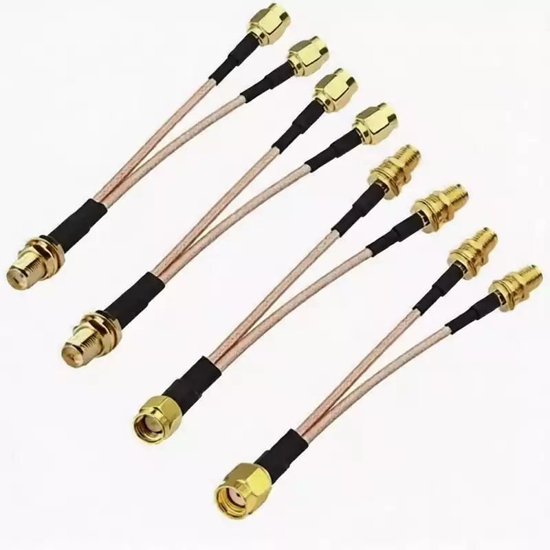
The manufacturing process at the connection point between the RF test cable and its connector is a critical detail determining its service life. Traditional test cables typically feature a rigid contact point between the cable and the connector. When equipment is frequently bent during use, the tension generated by bending is transmitted along the cable to these rigid contact points.
Long-term, repeated stress leads to ageing of the contact points and even cable breakage—a common fault frequently encountered by test engineers in practical operations. Such structural defects cannot be resolved simply by adding heat-shrink tubing, as the ageing and wear caused by the continuous transmission of stress cannot be mitigated by heat-shrink tubing alone.
In the case of traditional unarmoured RF test cables, the lack of protection from an armour layer means that even the installation of reinforced heat-shrink tubing at connection points cannot effectively delay ageing or extend service life. Furthermore, gaps often exist between the armour layers of traditional armoured cables, as well as between the armour and the signal transmission layer. Consequently, the tension generated by cable bending is still transmitted to the hard contact points, leading to issues such as fluctuations in electrical parameters and unstable test performance after prolonged use.
Addressing the shortcomings of traditional RF test cables, GORE’s innovative gap-free, tightly integrated inner armour design achieves structural optimisation. In this design, the tension and torque generated during cable bending are evenly distributed and absorbed by the mechanical armour layer, thereby significantly reducing the impact of stress on the hard contact points and the signal transmission layer. This ultimately ensures long-term stability of electrical parameters and significantly extends the service life of the cable.
The material of the connectors is also a key factor affecting the durability of RF test cables. There is a marked difference in durability between conventional copper outer conductor connectors and stainless steel connectors: under standard torque conditions, the effective service life of a copper connector is approximately 500 insertion/removal cycles, whereas a stainless steel connector can reach 5,000 cycles.
It should be noted that this figure represents the point at which performance begins to degrade according to factory standards, not the point at which the connector becomes immediately unusable; under actual operating conditions, the actual number of cycles a cable connector can withstand is typically far higher than this nominal value. For production testing scenarios requiring frequent plugging and unplugging, it is recommended to use adapters to effectively protect the RF test cable connectors and reduce signal loss.
From the perspective of application suitability, for static interconnections where frequent insertion, removal, or bending is not required, standard unarmoured RF test cables are sufficient to meet requirements. However, in scenarios such as high-volume mass production testing or intensive laboratory testing, armoured RF test cables offer superior long-term value for money due to their excellent stability and exceptionally long service life. Furthermore, there is a certain conflict between the structural design of flexible cables and the design principles for low passive intermodulation (PIM) performance; consequently, there are relatively few types of flexible RF test cables on the market that offer low PIM performance.
Superior performance and stable parameters are the core criteria for selecting RF test cables. Within the entire testing system, the impact of testing efficiency and product yield on overall production costs far exceeds the procurement cost of the RF test cables themselves. Only through a scientific and systematic approach to selection can testing benefits be truly maximised.