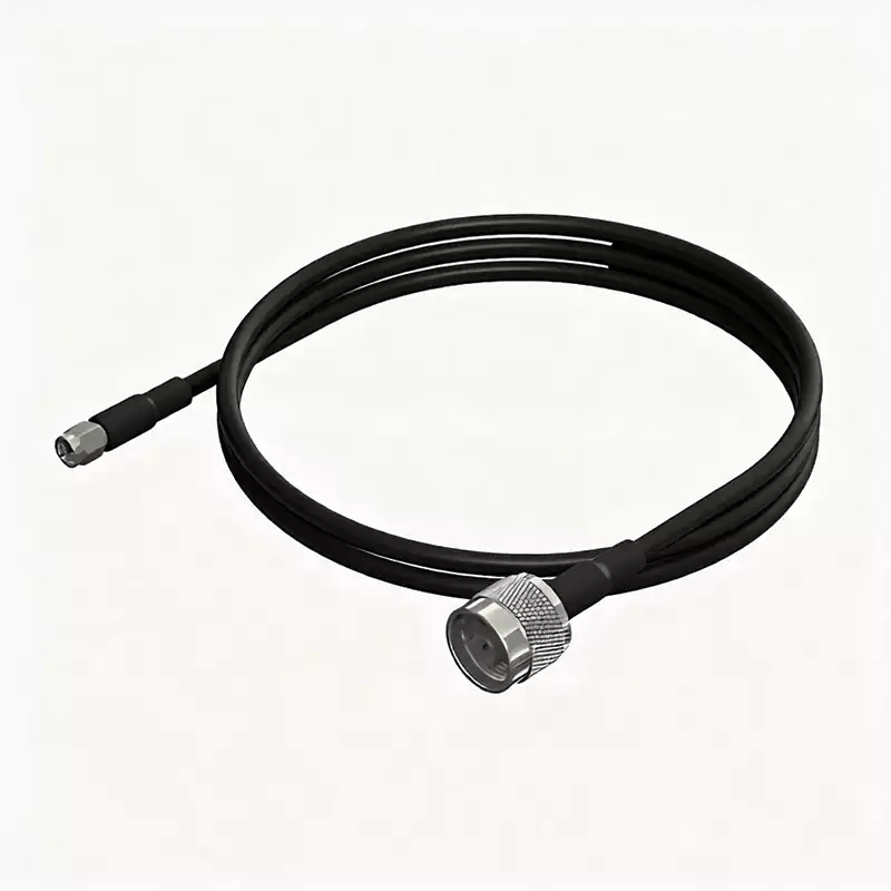
RF cable assembly is essential fundamental transmission components in RF and microwave systems. Their primary function is to enable low-loss, highly stable transmission of RF signals between different devices and modules. They are widely used in fields such as communication base stations, radar systems, satellite navigation, precision test equipment and wireless terminals. The complete assembly consists of a coaxial cable body and RF connectors precisely fitted at both ends; the degree of matching between the two directly determines the assembly’s transmission performance, operating frequency range and operational reliability.
Conventional coaxial rf cables employ a multi-layer coaxial symmetrical structure, consisting, from the centre outwards, of a central conductor, an insulating dielectric layer, an outer shielding conductor and a protective sheath. The central conductor is responsible for transmitting RF signals; the insulating dielectric layer provides electrical isolation between the inner and outer conductors; the outer shielding conductor suppresses external electromagnetic interference whilst preventing the leakage of internal RF signals; and the outermost sheath provides abrasion resistance, waterproofing, anti-ageing properties and mechanical protection. The accompanying RF connectors are designed with standardised impedance and frequency band matching, enabling precise connection to various RF equipment interfaces and ensuring the continuity and compatibility of signal transmission.
Main Categories and Differences in Characteristics of RF Cable Assembly
Flexible RF cables: These offer the greatest versatility and excellent flexibility, allowing for free bending and twisting, and flexible routing. They are suitable for cabling in confined spaces within equipment or in scenarios with complex routing paths. However, due to limitations in the braided shielding structure and materials, they have relatively high transmission losses and a lower power-carrying capacity, making them more suitable for conventional signal transmission at low frequencies, low power levels, and where frequent bending is required.
Semi-flexible RF cables: These feature moderate structural rigidity. Compared to flexible cables, they offer significantly reduced transmission loss, improved power handling capacity and better signal stability. The disadvantage is reduced mechanical flexibility, making them difficult to bend and shape at will; they are therefore primarily used for fixed internal cabling and medium-power RF signal transmission scenarios.
Semi-rigid RF cables: These feature extremely high structural rigidity and excellent dimensional stability. They offer extremely low transmission loss and high power capacity, with stable electrical performance, making them the preferred choice for high-precision RF systems. However, they cannot be bent by hand and require specialised forming tools for processing, resulting in a complex installation process. They are primarily used in scenarios with stringent requirements for transmission accuracy and power, such as base station RF links and precision test equipment.
Corrugated RF cable: A high-performance rigid cable featuring a corrugated design that combines the advantages of low loss and high power handling capacity with a degree of flexibility for bending adjustments. Offering greater installation adaptability, it is widely used in outdoor base station feeders and high-power RF transmission trunk lines.
Classification of RF Cables
By structural type: these are divided into coaxial RF cables, symmetrical RF cables and helical RF cables. Coaxial cables are the most widely used, achieving low-interference transmission through their symmetrical shielding structure; symmetrical cables are mostly used for low-frequency balanced signal transmission; helical cables possess retractable properties and are suitable for dynamic, mobile cabling scenarios.
By insulation type: These include solid-insulated cables, air-insulated cables and semi-air-insulated cables. Solid-insulated cables offer structural stability and good protection; air-insulated and semi-air-insulated cables have lower dielectric loss and superior transmission performance, and are frequently used for high-frequency, high-precision transmission.
By insulation material: These are categorised into plastic-insulated cables, rubber-insulated cables and inorganic mineral-insulated cables. Plastic insulation offers high cost-effectiveness and versatility; rubber insulation provides superior flexibility and weather resistance; inorganic mineral insulation possesses high-temperature resistance, flame retardancy and anti-ageing properties, making it suitable for high-temperature and harsh operating conditions.
By overall flexibility: categorised into flexible cables, flat flexible cables and rigid cables, which are respectively suited to internal equipment cabling, flat, orderly cabling and fixed trunk cabling in different installation scenarios.
By transmission power: cables rated below 0.5 kW are low-power cables (suitable for small terminal equipment); those rated between 0.5 and 5 kW are medium-power cables (suitable for conventional base stations and RF modules); and those rated above 5 kW are high-power cables (used in high-power transmission scenarios such as radar and large-scale transmission equipment).
Performance of RF Cable Assemblies
1.Characteristic Impedance
Characteristic impedance is the most fundamental and crucial electrical parameter of RF cables and assemblies, and it forms the basis for impedance matching design in RF systems. The prerequisite for a system to achieve maximum power transmission and minimum signal reflection is that the impedance of all connecting parts (cables, connectors, and equipment ports) is perfectly matched. If the match is ideal, signal transmission will only incur attenuation losses inherent to the cable itself, with no reflection losses; if there is a mismatch, this will result in signal reflection, power loss and distortion.
Characteristic impedance (Zo) is primarily determined by the structural dimensions of the inner and outer conductors and the properties of the insulating medium. Due to the skin effect, the signal propagates only along the surface of the conductors; therefore, the key influencing parameters are the outer diameter (d) of the inner conductor and the inner diameter (D) of the outer conductor. The calculation formula is:
Zo (Ω) = (138 / √ε) × log(D/d) (where ε is the dielectric constant of the insulating medium)
The standardised impedance system within the industry is as follows: 50 Ω is used in the vast majority of RF applications, such as communications, testing and radar; whereas 75 Ω is commonly used in broadcasting, television and cable video transmission systems to facilitate long-distance, low-loss transmission.
2.Voltage Standing Wave Ratio (VSWR) and Return Loss
VSWR and return loss are key indicators characterising the degree of impedance matching and the magnitude of signal reflection. When there is an abrupt change in impedance at a cable, connector or equipment interface, part of the incident signal is reflected; the superposition of the incident and reflected waves forms a standing wave, which affects transmission efficiency and system stability.
Voltage Standing Wave Ratio (VSWR) is defined as the ratio of the maximum voltage to the minimum voltage on a transmission line, and can be calculated using incident and reflected power:
VSWR = (1 + √(Pr/Pi)) / (1 – √(Pr/Pi)) (where Pr is the reflected power and Pi is the incident power)
The closer the VSWR is to 1, the better the impedance matching, and the superior the cable consistency and transmission stability.
Return loss is measured in decibels (dB); a higher value indicates lower reflection loss and better matching performance. The VSWR range for standard microwave RF cable assemblies is 1.1–1.5, corresponding to a return loss of 26.4–14 dB, with signal transmission efficiency reaching 96%–99.8%.
3.Attenuation (Insertion Loss)
Attenuation (insertion loss) quantifies the energy loss of RF signals during transmission through the cable and directly determines the cable’s effective transmission distance. Total loss consists of three components: conductor copper loss, dielectric loss and radiation loss; the vast majority of energy is converted into heat and dissipated.
Loss characteristics are closely related to frequency and structure: the larger the conductor cross-sectional area and the thicker the cable diameter, the lower the conductor loss; at higher operating frequencies, dielectric loss increases rapidly in a linear fashion, whilst conductor loss increases only by the square root of the frequency; consequently, dielectric loss dominates at high frequencies. An increase in ambient temperature also raises conductor resistance and increases the dielectric loss factor, thereby exacerbating attenuation.
The total insertion loss of a complete cable assembly comprises the loss within the cable itself, contact loss at the connectors, and loss due to impedance mismatch. Furthermore, usage practices (such as excessive bending or bending below the minimum bending radius) can also introduce additional loss. When selecting a cable for an application, one should first confirm the permissible loss threshold corresponding to the system’s highest operating frequency; provided the loss requirements are met, cables with the smallest possible wire gauge should be prioritised to balance performance and ease of installation.
4.Average Power Capacity
Average power capacity refers to the maximum average RF power that an RF cable can carry during long-term stable operation, and depends on the cable’s ability to withstand thermal losses and dissipate heat. In actual operating conditions, the effective power capacity is constrained by three major factors: VSWR matching, ambient temperature, and altitude. The correction formula is:
Effective power = Rated average power × VSWR × Temperature coefficient × Altitude coefficient
The higher the VSWR, the higher the temperature, and the higher the altitude (where air cooling is poorer), the lower the actual power capacity. When selecting cables for engineering applications, power redundancy must be factored in based on actual operating conditions to prevent cable damage caused by overheating due to overload.
5.Propagation Speed
Signal propagation speed refers to the ratio of the speed at which RF signals travel through the cable to the speed of light in a vacuum, expressed as a percentage. It is determined by the dielectric constant of the insulating medium:
Vp = (1 / √ε) × 100%
The lower the dielectric constant, the closer the propagation velocity is to the speed of light, and the shorter the transmission delay. Furthermore, low-density insulating media (such as foamed materials) not only enhance propagation velocity but also significantly reduce dielectric loss, making them the preferred solution for high-frequency, high-speed RF transmission.
6.Bending Phase Stability
Bending phase stability is a key indicator under dynamic operating conditions, characterising the degree of change in signal phase when the cable is bent. In high-precision systems such as precision testing, phase synchronisation and radar ranging,even minute phase shifts can directly affect equipment accuracy.
The smaller the bending radius, the greater the angle, and the higher the number of cycles, the more significant the phase shift becomes; moreover, phase variation is generally linearly proportional to the operating frequency.Compared to solid-core cables, low-density foamed-core cables exhibit lower structural stress and greater consistency in deformation, resulting in significantly improved bending phase stability, making them better suited for dynamic bending and high-precision transmission scenarios.
7.Passive Intermodulation Distortion
Passive intermodulation distortion is a critical latent parameter affecting RF systems with multiple coexisting signals, arising from the non-linear characteristics of the cable’s internal materials and structural contacts.An ideal RF system is linear, with input and output signal characteristics being identical and free of additional frequency components; however, actual cables contain non-linear defects such as gaps between metal contacts, material inhomogeneities and oxidation layers, which can cause signal distortion.
When two or more RF signals of different frequencies are transmitted simultaneously, these non-linear characteristics generate new spurious frequency components, known as intermodulation products. Among these,the most disruptive are third-order intermodulation products (2f1−f2, 2f2−f1), whose frequencies are highly likely to fall within the reception bands of equipment,causing signal interference, reduced sensitivity and communication errors. This severely affects the operational stability of multi-frequency coexistence communication systems and base station transceiver systems; consequently, it is a key testing parameter for high-end RF cable assembly.