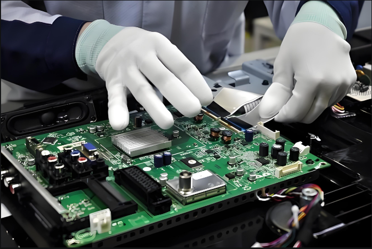
What is reflow soldering? Reflow soldering is a core soldering process in surface-mount technology (SMT), used to establish a mechanical connection and electrical continuity between the terminals or leads of surface-mount devices (SMDs) and the pads on a printed circuit board (PCB); it is a type of soft soldering. The basic principle involves remelting the paste-form soft solder (solder paste) pre-applied to the PCB pads, allowing the solder to wet the component leads and PCB pads at high temperatures, and forming a secure solder joint upon cooling and solidification.
Unlike traditional wave soldering, reflow soldering is only suitable for surface-mount devices and is not used for through-hole components. Its key feature is the uniform heating of solder joints via a hot air flow; the paste-like solder undergoes physical and chemical changes within a specific high-temperature airflow environment, ultimately completing the soldering process. The term ‘reflow soldering’ derives from the circulation of hot air within the machine, which creates a stable high-temperature environment. Solder melting and joining are achieved through this thermal reflow process, ensuring uniformity and consistency.
How Reflow Soldering Works
The reflow oven is the core piece of equipment for the reflow soldering process. It is typically divided into four temperature zones: the preheating zone, the hold zone, the reflow zone and the cooling zone. These zones are sequentially connected with a reasonable temperature gradient; only by precisely controlling parameters such as temperature and time in each zone can the defect rate be minimised and soldering quality ensured.
1.Preheating Zone
The function of the preheating zone is to gradually heat the PCB and surface-mount components from room temperature, allowing the solvents in the solder paste to evaporate slowly and activating the flux, thereby preparing for the subsequent soldering process. At the same time, it prevents the PCB and components from entering the high-temperature zone directly and suffering thermal shock, thus avoiding PCB warping and component damage (such as capacitor bursting or chip package cracking).
The key control factor is the heating rate. Excessively rapid heating causes severe thermal shock, leading to PCB warping, component lead de-soldering, or even component damage; conversely, too slow a heating rate results in insufficient solvent evaporation, making defects such as solder balls and voids more likely to occur during soldering.
Industry standards stipulate that the maximum heating rate should not exceed 4°C/s; in actual production, it is typically set at 1–3°C/s, and can be adjusted according to the PCB material, thickness, and component density. As the preheating zone heats up rapidly, there is a significant temperature difference between the front and rear sections of the furnace chamber; it is therefore necessary to ensure that the hot airflow is distributed evenly to avoid localised areas of excessively high or low temperature.
2.Holding Zone
The holding zone follows immediately after the preheating zone. Its primary purpose is to eliminate the temperature difference between the PCB and the components, allowing the temperature of the entire PCB and all components to stabilise and become uniform. Sufficient time must be allowed during the hold phase to enable components with higher thermal mass (such as QFP and PLCC integrated circuits) to gradually reach the same temperature as those with lower thermal mass (such as chip resistors and capacitors), ensuring consistent temperatures across all components.
Concurrently, the flux in the solder paste must be allowed to volatilise fully, allowing its chemical components to react with the oxides on the surfaces of the PCB pads and component leads, thereby removing the oxide layer and creating conditions for solder wetting.
The core requirement of the hold-temperature zone is ‘temperature uniformity’. By the end of this stage, oxides on all PCB pads, solder balls and component leads should be thoroughly removed, and the entire board should have reached thermal equilibrium (typically maintained at 150–180°C, depending on the type of solder paste). If the hold-temperature phase is insufficient, significant temperature variations between components may occur, leading to defects such as poor solder wetting, cold joints and bridging upon entry into the reflow zone.
3.Reflow Soldering Zone
The reflow soldering zone is the core temperature zone of the reflow process, where the solder melts and forms solder joints. Upon entering the reflow zone, the oven temperature rises rapidly, melting the solder paste. Under the action of the flux, the solder fully wets the PCB pads and component leads, forming a reliable connection.
Different solder pastes have different melting points: leaded solder paste (e.g. 63Sn37Pb) has a melting point of 183°C, whilst lead-free solder paste (e.g. 96.5Sn3Ag0.5Cu) has a melting point of 217°C. Therefore, the heater temperature in the reflow zone must be set to the maximum oven temperature to ensure the solder paste melts completely.
The peak temperature (maximum oven temperature) must be determined by taking into account the melting point of the solder, the heat resistance of the PCB substrate, and the heat resistance of the components: for lead-free solder paste, this is generally controlled between 230 and 250°C, whilst for leaded solder paste, it is controlled between 210 and 230°C.
Peak temperature control is critical: if too low, the solder paste will not melt completely, leading to defects such as cold solder joints, insufficient wetting and cold solder joints; if too high, it will cause the epoxy resin on the PCB substrate to char and delaminate, and plastic components to deform and fail, whilst also generating excessive eutectic metal compounds, making the solder joints brittle and reducing their strength.
Furthermore, the reflow time (the duration during which the solder remains in a molten state) must be strictly controlled; excessive duration not only damages internal furnace components but may also lead to component failure and scorching of the PCB.
4.Cooling Zone
The cooling zone is the final temperature zone in the reflow process, serving to rapidly cool the soldered PCB so that the molten solder solidifies quickly, forming stable and secure solder joints. The cooling rate directly affects the microstructure and mechanical strength of the solder joints.
Excessively slow cooling leads to the formation of excessive eutectic metal compounds in the solder, resulting in coarse grain structure, reduced joint strength, increased brittleness and a higher susceptibility to cracking; conversely, excessively rapid cooling may cause the PCB to warp or solder joints to detach due to excessive thermal stress. Industry standards generally specify a cooling rate of approximately 4°C/s for the cooling zone. Once the PCB temperature drops below 75°C (indicating the solder has fully solidified), the board can be removed from the oven and proceed to the subsequent inspection stage.
Having understood the operating principles of each temperature zone, it is necessary to adjust parameters such as the temperature of each zone and the conveyor belt speed appropriately, taking into account factors such as the PCB material, component type and solder paste grade, in order to minimise the rate of soldering defects. At the same time, reflow soldering equipment should be serviced and maintained regularly to promptly eliminate potential hazards and prevent equipment failures that could cause abnormal temperatures or speeds, thereby affecting soldering quality.
Reflow Soldering Workflow
Reflow soldering is primarily used for processing surface-mount PCBs. Depending on the assembly method, it is categorised into single-sided and double-sided assembly, with the key difference between the two being the number of assembly and reflow soldering cycles.
Single-Sided Assembly Process
This process is suitable for situations where components are mounted on only one side of the PCB, and the steps are straightforward:
Pre-application of Solder Paste: Use a screen printer to apply an appropriate amount of solder paste evenly onto the PCB pads, ensuring uniform thickness, no missed areas and no bridging.
Component Placement: Using manual or automated placement, precisely position surface-mount components (SMC/SMD) onto the solder-pasted pads, ensuring that the leads are aligned with the pads and that there is no misalignment, incorrect placement or missed components.
Reflow Soldering: The PCB with components attached is fed into the reflow oven, passing sequentially through the preheating, hold, reflow and cooling zones according to a preset temperature profile, thereby completing the entire process of solder melting, wetting and solidification.
Inspection and Electrical Testing: Following soldering, a visual inspection (solder joint quality, component placement) and electrical performance testing are conducted to identify defects such as cold solder joints, bridging and incorrect placement.
Double-Sided Assembly Process
Applicable when components need to be mounted on both sides of the PCB, requiring two assembly runs and two reflow soldering cycles:
Pre-application of solder paste on Side A: Solder paste is screen-printed onto Side A of the PCB (typically the side with lower component density).
Side A component placement: Components are precisely placed onto the pads on Side A.
Side A Reflow Soldering: The board is fed into the reflow oven to complete soldering on Side A, then removed once cooled.
Side B Solder Paste Application: The board is flipped, and solder paste is screen-printed onto Side B (typically the side with higher component density), taking care to avoid damaging the components and solder joints already attached to Side A.
Side B Component Placement: Components are placed on Side B.
Side B Reflow Soldering: The board is returned to the reflow oven to complete soldering on the B-side. Care must be taken to adjust the temperature profile to prevent damage to the solder joints on the A-side due to re-heating.
Inspection and Electrical Testing: A comprehensive inspection is carried out to assess the quality of solder joints and component placement on both sides, followed by electrical performance testing.
Requirements for the Reflow Soldering Process
Reflow soldering is a process in electronics manufacturing that demands a high degree of precision. Its key advantages lie in the ease of precise temperature control, the effective prevention of solder and pad oxidation, and controllable costs. To ensure soldering quality, the following requirements must be adhered to:
Temperature Profile Control: Set appropriate reflow temperature profiles (including temperatures for each zone, ramp rates, dwell times, reflow duration and cooling rates) based on the PCB material, component type and solder paste grade. Conduct regular testing and calibration to ensure parameter stability.
Soldering Direction Requirements: Solder in the direction specified by the PCB design to ensure that the hot air flow evenly covers every area, thereby avoiding localised temperature inconsistencies.
Conveyor belt stability: Strictly prevent conveyor belt vibration, as this may cause component displacement or overflow of molten solder, resulting in defects such as bridging or cold solder joints. Regular inspection and maintenance are required.
First-piece inspection: Prior to each production batch, conduct a comprehensive inspection of the first printed circuit board; mass production may only commence once it has been confirmed as compliant, thereby avoiding batch defects.
Soldering Quality Inspection: During mass production, soldering quality must be inspected at regular intervals, with particular attention paid to: whether the solder has melted sufficiently; whether the solder joint surface is smooth; whether the solder joint shape is a standard crescent; the presence of solder balls and residues; and instances of bridging or cold solder joints. Simultaneously, check for colour changes on the PCB surface to determine if overheating has occurred. Adjust the temperature profile promptly based on the inspection results.
Factors Affecting the Reflow Soldering Process
Soldering quality is influenced by a variety of factors. In addition to temperature profiles and operating specifications, these include:
Differences in component thermal capacity: Integrated circuits such as PLCCs and QFPs have a much higher thermal capacity than discrete components such as chip resistors and capacitors; they require more heat to be absorbed during soldering in order to reach the solder melting temperature. This must be accommodated by adjusting the temperature profile (e.g. extending the dwell time or increasing the peak temperature).
Impact of equipment heat dissipation: The conveyor belt in a reflow oven dissipates a significant amount of heat during the cycle; heat dissipation conditions differ between the edges and the centre of the oven chamber, with edge temperatures typically being lower, resulting in temperature variations within the same cross-section. This must be compensated for by adjusting the distribution of hot air flow and optimising the temperature profile.
Impact of product load: The stability of the temperature profile is closely related to the product load. Load factor LF = L/(L+S) (where L is the length of the assembled PCB and S is the spacing between PCBs). The higher the load factor, the greater the heat dissipation, the more difficult it is to control the temperature profile, and the poorer the repeatability. Typically, the maximum load factor range for a reflow oven is 0.5–0.9; the load must be controlled appropriately based on the product specifications and equipment model.
Reflow Soldering Operating Procedures
A standardised operating procedure is fundamental to ensuring soldering quality and production safety:
Equipment Inspection and Preparation: Before switching on the machine, check the interior of the furnace chamber for any debris or residual solder dross; thoroughly clean the furnace chamber, conveyor belt and hot air outlets; confirm that safety guards are in good working order before switching on the power supply, select the appropriate production programme, and enter the temperature settings interface.
Equipment Parameter Adjustment: Adjust the guide rail width to match the PCB board width; activate the air circulation system, mesh belt conveyor system and cooling fans, and check that they are operating normally.
Temperature Parameter Settings: Set temperatures strictly in accordance with process requirements based on the soldering type (lead-containing/lead-free): maximum temperature for lead-containing products (245±5)°C, and for lead-free products (255±5)°C , preheat temperature 80–110°C; simultaneously set the conveyor belt speed and temperatures for each zone, and record the equipment’s operating parameters daily.
Heating-up and trial production: Switch on the heating controls for each zone in sequence. Once the temperature has risen to the set value and stabilised, begin feeding PCBs for soldering. Pay attention to the direction of conveyance to ensure the pads are correctly oriented, and that the spacing between any two consecutive PCBs is no less than 10 mm.
Incoming Inspection: Re-confirm that the conveyor belt width and flatness are compatible with the PCBs. Check the batch number, model and technical specifications of the boards to be processed to ensure they match the production procedure and to prevent cross-contamination.
Soldering Process Control: For small reflow ovens, control the soldering time and temperature to prevent copper foil blistering. After soldering, the joints should be smooth and shiny, with all pads uniformly tinned. Boards with poor soldering must be re-soldered, but this must only be carried out once they have cooled completely.
Quality Inspection and Recording: Wear heat-resistant gloves when handling soldered PCBs, touching only the edges of the boards. Take 10 samples per hour for spot checks, inspecting the quality of the solder joints and component placement, and record the findings. If any parameter abnormalities are detected during production, do not adjust the settings yourself; notify a technician immediately.
Temperature Profile Testing: Test the temperature profile regularly. Insert the temperature sensor into the tester’s receiver socket, switch on the power, and place the tester together with the PCB into the reflow oven. Remove it after soldering is complete, read the data via a computer, and adjust the temperature parameters accordingly.
Product Organisation: Store PCBs that have passed soldering inspection by order number, product name, etc., and label them clearly to prevent mix-ups and the production of defective items.
Reflow Soldering Operating Precautions
Reflow soldering equipment operates at high temperatures; safety regulations must be strictly observed during operation:
Safety Protection: Do not touch the conveyor belt, furnace chamber or other high-temperature components to prevent burns; do not allow liquids such as water or oil, or debris, to fall into the furnace chamber to avoid equipment failure or safety incidents.
Ventilation and Protection: Soldering generates a small amount of fumes; ensure the production area is well-ventilated and that the exhaust duct leads to the outside. Operators must wear work clothes and face masks to ensure personal protection.
Equipment Safety: Regularly inspect the wiring in heating areas to prevent electrical leakage caused by ageing or damage; periodically check electrical and pneumatic circuits to identify potential safety hazards.
Operational Guidelines: Before commencing work, ensure clothing is tidy; remove name badges, necklaces and other accessories; and tuck in sleeves to prevent clothing or accessories from becoming entangled in the conveyor belt.
Parameter Management: Parameters such as temperature zones and conveyor belt speed for reflow soldering are determined through rigorous calibration and must not be altered arbitrarily; should adjustments be required, these must be carried out by qualified technical personnel to prevent equipment damage or batch defects caused by abnormal parameters.
As a core process in SMT, the precise control of the temperature profile and standardised operation of the reflow soldering machine directly determine the soldering quality and long-term reliability of electronic products.Only by thoroughly understanding the principles of each temperature zone, strictly adhering to process requirements, and continuously optimising production details can the full potential of reflow soldering be realised, providing a solid foundation for the manufacture of high-density,highly integrated electronic components.